
Walk into the control room of a water utility, a pipeline operations center, or a large manufacturing plant and you’ll usually find the same thing: a handful of operators sitting in front of large monitors, watching a live schematic of equipment that might be spread across an entire city or hundreds of miles of pipeline. That’s SCADA at work – Supervisory Control and Data Acquisition – and it’s one of the most important but most frequently misunderstood layers of industrial automation.
The confusion is understandable. SCADA, PLC, and DCS all get used interchangeably in casual conversation, and job postings often list them as if they were competing skills rather than complementary layers of the same control system. This article clears that up. You’ll learn what SCADA actually is, the five components every SCADA system is built from, how data physically flows from a field sensor to an operator’s screen, and exactly where SCADA’s boundaries are relative to PLC and DCS – one of the most common follow-up questions once the basic definition clicks.
SCADA Defined in Plain Terms
SCADA stands for Supervisory Control and Data Acquisition. Strip away the acronym and the name is actually a fairly literal description of the job it does: it acquires data from equipment in the field, and it lets a human supervise and, when needed, control that equipment from a central location -without needing to physically be at each piece of equipment.
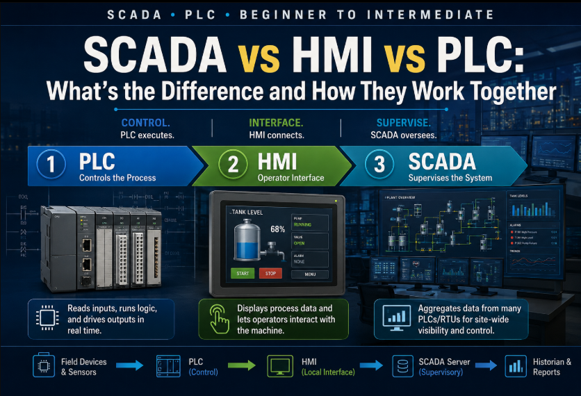
The key word is supervisory. SCADA is not usually the layer making split-second control decisions – that fast, local decision-making happens in PLCs (programmable logic controllers) or RTUs (remote terminal units) out in the field, close to the actual equipment. SCADA sits above that layer. It collects the status and data those field devices are already producing, displays it to a human in a form they can act on, stores a history of it, and passes down high-level commands – start this pump, open that valve, change this setpoint – that the field devices then execute.
This is why SCADA is so strongly associated with geographically distributed systems: water and wastewater utilities, oil and gas pipelines, electrical grids, and large multi-building manufacturing sites. Any of these could rely on dozens or hundreds of individual PLCs and RTUs scattered across a wide area, each perfectly capable of running its own local process – SCADA is what stitches all of that into one coherent picture for the people responsible for running the whole system.
The Five Core Components of a SCADA System
Almost every SCADA system, regardless of industry or vendor, is built from the same five layers. Understanding these five is really understanding SCADA.
1. Field Devices: RTUs and PLCs
At the bottom of the architecture are the field devices that talk directly to the physical process – sensors, actuators, motors, and valves. An RTU (remote terminal unit) or a PLC sits close to this equipment, reads its sensors, executes local control logic, and packages the resulting data to send upstream. RTUs were historically the more common choice for widely distributed assets like pipelines because of their low power draw and native support for slow or unreliable communication links; PLCs have increasingly taken over this role as they’ve become more rugged and communication-capable, and the line between the two device types has blurred considerably.
2. Communication Network
Connecting field devices back to the central system requires a communication network, and the physical medium varies enormously depending on how spread out the equipment is. A single plant might use a wired Ethernet network end to end. A pipeline spanning hundreds of miles might rely on radio telemetry, leased telephone lines, cellular data, or satellite links for the remote segments, often bridging several of these within one system.
3. Central SCADA Server (Master Terminal Unit / MTU)
The central server – sometimes called the master terminal unit or MTU – is where field data actually arrives, gets organized, and gets acted on. It polls or receives data from every connected RTU and PLC, maintains the current status of every point in the system, executes any supervisory logic, and issues commands downstream when an operator (or an automated rule) calls for one. In larger systems this server role is often split across redundant, clustered machines so a single hardware failure doesn’t blind the control room.
4. Human-Machine Interface (HMI)
The HMI is the operator’s window into the system – the graphical screens showing tanks, pipelines, pumps, and alarms, usually laid out as a schematic that mirrors the physical plant. Operators use the HMI to monitor status, acknowledge alarms, and issue supervisory commands like starting a pump or changing a setpoint. A well-designed SCADA HMI follows a clear visual hierarchy so that an abnormal condition is immediately obvious against a calm, uncluttered baseline screen.
5. Historian
The historian is a specialized database that archives time-stamped process data – often years of it – at a resolution far higher than would be practical to keep in a general-purpose database. It’s what makes long-term trending, regulatory compliance reporting, root-cause investigation after an incident, and statistical process analysis possible. Without a historian, a SCADA system can tell you what’s happening right now, but it can’t tell you what happened at 3 a.m. three weeks ago.
How Data Flows from Field Sensor to Operator Screen
It helps to trace one piece of data all the way through the system; from the moment it’s physically measured to the moment an operator sees it change on screen.
| 1. Field sensor measures a physical value | e.g. a pressure transmitter reads 42.3 psi | 2. RTU/PLC converts and reads the signal | analog 4-20mA signal -> scaled engineering value | 3. RTU/PLC sends the value over the network | via Modbus, DNP3, or another SCADA protocol | 4. Central SCADA server receives and stores the value | updates the live database, checks alarm limits | 5. HMI displays the updated value | pressure gauge graphic updates on the operator’s screen | 6. Historian logs the value with a timestamp | available later for trending and reporting |
This entire round trip typically happens in well under a second for most conventional SCADA polling rates, though the exact speed depends heavily on the communication medium – a plant-floor Ethernet link updates far faster than a radio-linked RTU checking in every few seconds out on a remote pipeline segment. When an operator responds to that pressure reading by clicking a button to open a relief valve, the same path runs in reverse: HMI to server to network to RTU/PLC, which then actually energizes the physical output.
SCADA vs PLC: What’s the Difference?
This is one of the most common points of confusion for anyone new to automation, largely because a PLC is usually a component inside a SCADA system rather than a competing alternative to it. The distinction is really one of scope and role, not of one being a de facto “upgrade” of the other.
A PLC is a single piece of hardware executing real-time control logic for a specific piece of equipment or process – reading its own inputs, running ladder logic or structured text, and driving its own outputs, all within a tightly bounded scan cycle measured in milliseconds. A SCADA system, by contrast, is the layer that sits above potentially many PLCs (and RTUs), aggregating their data, presenting it to human operators, and issuing high-level supervisory commands. A PLC can run its process completely independently even with no SCADA system watching it at all – SCADA is optional from the process’s point of view, but essential from the operator’s point of view once a facility grows past what one person can watch locally.
A useful rule of thumb: if the question is “what decides, in real time, whether this valve opens right now,” that’s a PLC question. If the question is “how does an operator two buildings away see that the valve just opened and know whether that’s normal,” that’s a SCADA question.
SCADA vs DCS: When Each Architecture Fits
The comparison with DCS (distributed control system) is subtler, because both SCADA and DCS provide supervisory visibility and centralized operator interfaces – the difference is architectural philosophy and the kind of process each was originally built for.
A DCS is designed around a tightly integrated, redundant control architecture native to a single large, continuous process – think an oil refinery or a large chemical plant – where control and supervisory functions are unified in one vendor’s engineering environment from the ground up, with redundancy built in at nearly every layer by default. SCADA architectures historically grew up around geographically distributed assets where different sites might even run different vendors’ PLCs and RTUs, connected together over a comparatively loose, protocol-based communication layer rather than one unified backbone.
| Attribute | SCADA | DCS |
| Typical use case | Geographically distributed assets (pipelines, utilities, multi-site plants) | Single large continuous process (refinery, chemical plant) |
| Control architecture | Distributed field controllers, communication-layer integration | Tightly integrated, natively redundant control architecture |
| Vendor mix | Often multi-vendor field devices under one SCADA platform | Usually single-vendor, unified engineering environment |
| Communication | Polled/networked over varied media (radio, cellular, Ethernet) | High-speed proprietary or industrial backbone, low latency |
| Redundancy | Added where needed, often at the server/historian layer | Built in by default at nearly every layer |
In practice the line has blurred considerably – modern DCS platforms now offer SCADA-style remote monitoring, and modern SCADA platforms can run process control logic that looks a lot like a small DCS. The distinction matters most when choosing an architecture for a new project rather than when analyzing an existing one, and increasingly the honest answer to “SCADA or DCS” is that the platforms have converged enough that the choice comes down to vendor ecosystem and existing plant standards as much as any fundamental architectural difference.
A Worked Example: Water Treatment Plant SCADA
A municipal water treatment plant is one of the clearest illustrations of SCADA because the process is intuitive and the geographic spread is real: a raw water intake, a treatment plant, and multiple distribution pump stations and storage tanks scattered across a service area.
- Field level: PLCs at the intake control raw water pumps; PLCs at the treatment plant control chemical dosing, filtration, and disinfection; RTUs at remote pump stations and elevated storage tanks monitor tank level and pump status.
- Communication: the treatment plant itself runs on a wired Ethernet network; remote pump stations and tanks, often miles apart, report in over cellular or licensed radio links back to the central SCADA server.
- Central server: aggregates the current status of every tank level, every pump, every chlorine residual reading, and every alarm across the entire service area into one live database.
- HMI: operators in the central control room see a system-wide schematic – tank levels represented as filling bar graphs, pump run/fault status as colored icons, and any alarm (e.g. low chlorine residual, high turbidity) surfaced immediately and audibly.
- Historian: chlorine residual, turbidity, flow rate, and pressure are logged continuously, which is exactly the data set regulators require utilities to retain and be able to report on for water-quality compliance.
If a remote storage tank’s level drops faster than normal overnight, the RTU reports the falling level, the SCADA server flags it against expected consumption patterns, the HMI raises an alarm for the on-call operator, and that operator – sitting at a desk possibly twenty miles from the tank – can remotely start an additional distribution pump to compensate, all without a truck rolling out to the site first. That end-to-end capability, spanning a wide geographic area from a single control room, is the entire value proposition of SCADA in one example.
Common SCADA Communication Protocols
- Modbus (RTU and TCP) – one of the oldest and most widely supported industrial protocols, valued in SCADA for its simplicity and near-universal device support, though it lacks native security features.
- DNP3 (Distributed Network Protocol) – particularly common in electric utility and water/wastewater SCADA, designed with unreliable, low-bandwidth communication links in mind and with better built-in support for time-stamped event data than Modbus.
- OPC UA – a modern, platform-independent standard for secure, structured data exchange between control systems and higher-level software, increasingly the preferred choice for new SCADA-to-enterprise integration.
- IEC 60870-5-101/104 – widely used in electric power SCADA outside North America, roughly filling the same role DNP3 fills domestically.
- MQTT – a lightweight publish/subscribe protocol increasingly used for SCADA data destined for cloud platforms or IIoT applications, valued for working well over constrained or intermittent connections.
SCADA Cybersecurity Basics (Overview)
SCADA systems were historically designed assuming a trusted, isolated network, and many of the oldest and most common protocols – Modbus chief among them – carry no built-in authentication or encryption at all. As SCADA systems have connected to corporate IT networks and, increasingly, the internet for remote access and cloud reporting, that assumption has become a genuine liability, and industrial control system security has become its own specialized discipline.
At a foundational level, SCADA cybersecurity rests on a few widely recommended practices: network segmentation that keeps control-system traffic separate from general corporate IT traffic (often using a demilitarized zone between the two); strict access control and multi-factor authentication for any remote access into the SCADA network; regular patching of the server and HMI operating systems, which are typically standard Windows or Linux machines despite running specialized software; and continuous monitoring for anomalous traffic on a network where legitimate behavior is usually far more predictable than on a typical office network. This is a deep field in its own right – the NIST industrial control systems security guide is a solid starting point for going further than this overview.
FAQ: SCADA Questions Answered
What does SCADA stand for?
SCADA stands for Supervisory Control and Data Acquisition. It describes a system that acquires data from field equipment like sensors and PLCs, presents that data to human operators through an HMI, and allows operators to issue supervisory commands back down to that equipment from a central location.
What is the difference between SCADA and PLC?
A PLC is a single controller running real-time logic for one process or machine, executing independently of any supervisory system. SCADA is the layer above potentially many PLCs and RTUs that aggregates their data, displays it to operators, and sends down high-level commands. A PLC can run without SCADA; SCADA exists to give operators visibility across many PLCs at once.
What is a SCADA historian?
A historian is a specialized database within a SCADA system that archives time-stamped process data at high resolution, often for years. It enables long-term trending, regulatory compliance reporting, and root-cause investigation, filling a role that a live SCADA display alone cannot – showing what happened in the past, not just what’s happening now.
Is SCADA the same thing as a DCS?
No, though they overlap in purpose. SCADA architectures traditionally suit geographically distributed, often multi-vendor assets like pipelines and utilities, communicating over varied networks. DCS architectures suit a single large continuous process, like a refinery, with tightly integrated, natively redundant control built in from the ground up. Modern platforms have blurred this line considerably.
Do small facilities need SCADA, or is a PLC with an HMI enough?
A single machine or small process with one local operator screen usually doesn’t need full SCADA – a PLC with a local HMI is sufficient. SCADA earns its place once there are multiple sites, remote or unstaffed locations, or a need for centralized historical data and alarm management across more equipment than one person can watch by walking the floor.
Key Definitions
RTU (Remote Terminal Unit): A field device that reads sensors and controls equipment at a remote site, then communicates that data back to a central SCADA server, often over radio, cellular, or other long-distance links.
Historian: A specialized database that archives time-stamped process data at high resolution over long periods, enabling trending, compliance reporting, and after-the-fact investigation that a live display alone cannot provide.
HMI (Human-Machine Interface): The graphical operator interface in a SCADA system, typically showing a schematic of the physical process, current equipment status, active alarms, and controls for issuing supervisory commands.
Supervisory Control: High-level command authority – such as starting a pump or changing a setpoint -issued by an operator or central system to field devices, which then carry out the actual real-time execution locally.
Further Reading
- How to Set Up a Modbus TCP Connection Between a PLC and SCADA
- Ignition SCADA Tutorial
- SCADA vs DCS vs PLC
External References
- ISA (International Society of Automation) SCADA resources
- NIST industrial control systems security guide
About The Author