
Every traffic light in every city uses the same basic method: a chain of timers that quietly count and pass control to each other in turn, running on their own without anyone pressing buttons.
This timer-driven sequence that loops on its own is one of the first real automation concepts every PLC programmer should learn. While traffic lights may not seem exciting, this same structure is used in conveyor indexing, filling machines, packaging lines, wash-down cycles, and many other repetitive industrial tasks.
In this tutorial, you’ll build that structure from the ground up on a Mitsubishi FX3U PLC. You’ll wire a start button and a three-color stack light, write ladder logic with cascaded on-delay timers, and, unlike most beginner tutorials, you’ll set up the sequence to restart itself automatically when it finishes.
This article is a companion to the Bob Teaches Tech YouTube video for this build. The video shows the sequence in real time, while this article breaks it down step by step. Each rung is explained, every timer is covered, and common ‘what if I remove this’ questions are answered ahead of time.
By the end, you’ll have more than a working traffic-light demo. You’ll understand this pattern well enough to use it in real machines.
Understanding PLC Loop Sequences
What Is a PLC Loop Sequence?
A PLC loop sequence is a program structure where a series of steps run in order, and when the last step finishes, the program automatically returns to the first step and starts again, all without any operator input.
The loop is what sets an industrial sequence apart from a classroom demo. A one-shot sequence proves your logic works once. A looping sequence shows your machine can run by itself for an entire shift, which is the real goal of automation.
Why Are Timers Used?
Timers are the easiest way to give a sequence a set duration, like how long a lamp stays on, how long a valve stays open, or how long a conveyor moves before stopping. In Mitsubishi FX PLCs, an on-delay timer (the standard TON-style timer) starts counting as soon as its input condition is true, and its output contact closes only after the preset time has passed.
If you connect several on-delay timers so that each one starts the next when it finishes, you create a self-advancing sequence. There are no jumps, subroutines, or complicated state machines; just timers handing control to each other.
What Is an Internal Relay?
An internal relay (M-device on Mitsubishi FX PLCs, also called a marker or auxiliary relay) acts like a physical relay coil, but it only exists in the PLC’s memory. You can turn it on or off and use its contacts anywhere in the program, as many times as you need.
In this project, M0 acts as the master run relay. Instead of wiring the start button’s logic into every rung, you energize M0 once and let the other rungs use M0’s contact. This is a good habit to learn early, since real machines often use a few master relays to control the rest of the program through many interlocks.
Timer-Based vs. Counter-Based Sequencing
Timer-based sequencing moves to the next step after a set amount of time has passed. This is useful when you want a transition to happen on a schedule, like a lamp staying on for exactly three seconds no matter what else is happening.
Counter-based sequencing moves to the next step after a certain number of events, like a part passing a sensor, a button being pressed several times, or a cycle repeating a set number of times. Here, the step change depends on activity, not on time.
Many real machines use both methods together. For example, a timer can control how long a lamp stays on, while a counter tracks how many full cycles have finished before sending a batch-complete signal. We’ll discuss how to combine both approaches in the Future Improvements section.
Hardware Required
Here is a list of everything used in the build. All of these are standard PLC training kit components, and most have direct industrial-grade equivalents you will see on real panels.
| Component | Purpose | Recommended Alternatives | Est. Price | Industrial Equivalent |
| Mitsubishi FX3U PLC | Main controller -executes the ladder logic | FX3G, FX3S, or any FX-series CPU with enough I/O | $150–$400 (used/refurb often lower) | FX3U-series CPU on a DIN-rail panel |
| 24V DC Power Supply | Powers the PLC and field devices | Any regulated 24V DC supply rated for your load (aim for 20–30% headroom) | $25–$60 | DIN-rail switch-mode 24V PSU (e.g., Mean Well) |
| Push-button module (SB1) | Start input for the sequence | Panel-mount illuminated pushbutton, momentary N.O. contact block | $5–$20 | 22mm illuminated momentary pushbutton |
| 3-colour stack light | Visual output – red / yellow / green lamps | Individual panel-mount pilot lamps, LED tower light | $20–$70 | Signal tower light (e.g., Patlite / Banner) |
| Terminal blocks & DIN rail | Clean, serviceable wiring termination | Any DIN-rail terminal block system | $10–$30 | Phoenix Contact or Wago DIN-rail terminals |
| 22–24 AWG stranded wire | Field wiring for inputs/outputs | Pre-made jumper leads for training benches | $5–$15 | UL1015/UL1007 panel wire |
| USB / RS-422 programming cable | Connects GX Works2 on your PC to the PLC | USB-SC09-FX equivalent cable | $15–$40 | Same cable – used in the field too |
Prices are approximate and can vary by region and supplier. Always check the current price before ordering.
Explaining the PLC Wiring
Power Supply
Start with the power supply, because nothing else will work until this is set up correctly. The 230V AC mains connects to the power supply’s input terminals: Live, Neutral, and Earth. Always treat these terminals as live and isolate the circuit before touching anything.
On the output side, the power supply provides +24V DC and 0V (common). These two terminals feed the PLC’s power input and, in most training setups, also feed the field devices, the push button, and the stack light.
Wiring the Input (SB1)
SB1, the green start push button, is a normally-open momentary contact. One side connects to the PLC’s common input terminal (S/S), and the other side connects to input X0.
When you press SB1, it completes the circuit and X0 becomes true in the PLC’s input image register. When you release the button, X0 returns to false. That’s the whole input side of this project: one button, one bit.
Wiring the Outputs (Stack Light)
The stack light has four wires: one common (usually black) and three signal wires, one per lamp color. Wire the common back to the PLC’s output common rail, then wire red to Y000, yellow to Y001, and green to Y002.
Always check the lamp assembly’s rated voltage before turning it on. Most training kit stack lights use 24V DC to match the PLC’s I/O, but some industrial towers need 24V AC or even 120/230V AC from a separate supply.
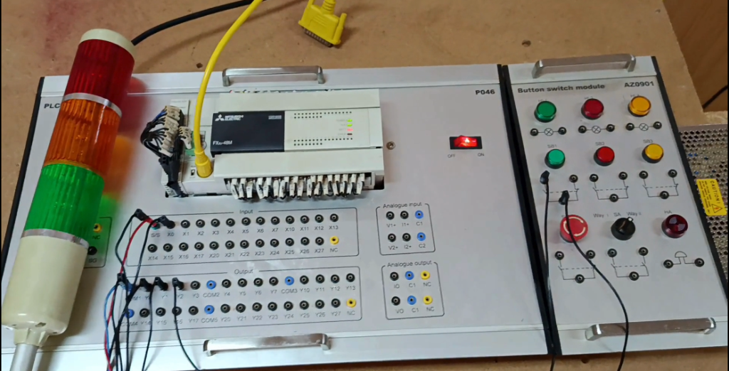
Figure 1. Power, input, and output wiring for the FX3U traffic-light loop sequence
PLC Addressing
PLC addressing is a naming system that tells the CPU which physical terminal a piece of logic refers to. On Mitsubishi FX PLCs, inputs use X (X0, X1, X2, etc.) and outputs use Y (Y000, Y001, Y002, etc.), usually in octal.
Internal relays use M (M0, M1, and so on), and timers use T (T0, T1, etc.). Once you can read an address and picture the physical terminal or memory bit it refers to, ladder logic becomes much easier to understand.
Sourcing vs. Sinking Inputs
Sourcing and sinking describe the direction of current flow in an input circuit. This can be confusing for beginners, especially when wiring a PLC that is set up differently from their training kit.
In a sinking input configuration, the PLC’s input terminal supplies (sources) the positive voltage, and the field device switches the 0V (common) side-current “sinks” into the PLC. In a sourcing configuration, it’s reversed: the field device supplies positive voltage to the input, and the PLC’s common is tied to 0V.
FX3U inputs let you choose the mode depending on how you wire the S/S terminal. If your button does not register presses even though the wiring looks correct, mismatched sourcing or sinking is one of the first things to check. We’ll cover this again in the Troubleshooting Guide.
GX Works2 Setup – A Complete Beginner Guide
Everything below assumes you’re starting from a blank GX Works2 installation and a PLC that’s never been programmed before.
1. Open GX Works2 and start a new project: Launch GX Works2 and select “New Project.” This is the correct software for FX3U (GX Works3 targets the newer iQ-F/iQ-R families).
2. Select the PLC series and type: Choose “FXCPU” as the series, then select FX3U as the specific PLC type. Getting this wrong won’t stop you from writing logic, but it can cause instruction or addressing mismatches later.
3. Choose Ladder as the programming language: Select Ladder from the language options and create a Simple Project (as opposed to a Structured Project); this matches the classic ladder style used throughout this tutorial.
4. Configure the communication settings: Under Online → Transfer Setup, select the correct connection type (USB is simplest for a bench setup) and the COM port your programming cable is enumerated as in Device Manager.
5. Put the PLC in STOP mode: Before writing any new program, switch the physical RUN/STOP switch on the PLC to STOP. Downloading a program while the PLC is running the old one is asking for unpredictable behavior.
6. Clear the PLC memory: Use Online → PLC Memory Operation → Clear PLC Memory to wipe any previous program and reset device values. Skipping this step is a common source of “ghost logic”-old rungs interacting with your new ones.
7. Write and verify your ladder logic: Build the rungs described in the Ladder Logic Walkthrough section below. Use Convert (or Convert All) frequently; GX Works2 won’t let you download logic that hasn’t been successfully converted.
8. Download the program: With the PLC still in STOP mode, go to Online → Write to PLC, select your program, and download. GX Works2 will prompt you to confirm, EXECUTE, and wait for the transfer to complete.
9. Switch to RUN mode: Flip the PLC’s physical switch to RUN, or set it remotely if your CPU supports it. The PLC will now begin scanning and executing your logic continuously.
10. Monitor the program: Go to Online → Monitor → Monitor Mode. You’ll see live highlighting on energized contacts and coils, which is invaluable for confirming the sequence is actually doing what you designed.
11. Debug using device monitoring: If something isn’t behaving, open a Device/Buffer Memory Batch Monitor and watch X0, M0, and T0 to T4 directly. Watching raw device states, rather than just the ladder view, often reveals timing issues faster.
Ladder Logic Walkthrough
Instead of giving you a finished program to copy, we’ll build it rung by rung, just like you would work through it on a whiteboard. The complete logic uses five timers (T0 to T4), one internal relay (M0), one input (X0), and three outputs (Y000 to Y002).
Before we start, note that the video does not give an exact preset for the yellow lamp’s timer (T2). In this walkthrough, we use 3.0 seconds (K30), the same as the red to yellow transition, just for symmetry. Use this as a starting point and adjust the timing as you prefer for your own build.
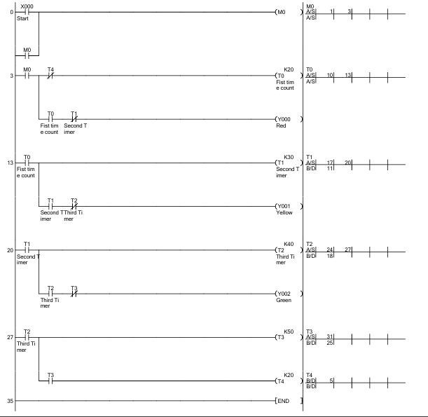
Figure 2. Complete ten-rung ladder program for the automatic timer loop sequence
Rung 0: X0 seals in M0 (the master run relay)
LD X0, OR M0, OUT M0
Pressing SB1 (X0) energises M0. In parallel with X0, we wire a contact of M0 itself feeding back into the same rung, a seal-in (or “latching”) circuit. Once M0 turns on, its own contact keeps the rung true even after you release the button and X0 drops out.
If this rung were removed: Without the seal-in contact, M0, and everything downstream of it, would only stay energized for as long as you physically held the button down. You’d have to hold SB1 for the entire 15-second cycle, which defeats the point of a start button.
Rung 1: M0 starts Timer T0 (K20 = 2.0s)
LD M0, OUT T0 K20
M0 being true starts T0 counting. T0 is a 2-second on-delay timer – its own contact won’t close until 2.0 seconds after M0 turns on. This is the startup delay before the red lamp appears.
If this rung were removed: Remove this rung and nothing downstream ever starts – T0 is the trigger for the entire chain. The sequence would sit at M0 = ON forever with all lamps off.
Rung 2: T0 done starts Timer T1 (K30 = 3.0s)
LD T0, OUT T1 K30
Once T0’s 2 seconds elapse, its contact closes and starts T1 counting a fresh 3-second interval. T1’s eventual completion is what will turn the red lamp back off and the yellow lamp on.
If this rung were removed: The red lamp would turn on (from the next rung) but would never turn off, since nothing would ever open the holding contact that keeps Y000 energized.
Rung 3: Red lamp ON while T0 is done and T1 is not yet done
LD T0, ANI T1, OUT Y000
This is the rung that actually drives the red lamp. T0’s contact (closed) in series with T1’s normally-closed contact (still closed, because T1 hasn’t finished yet) energizes Y000. The moment T1 finishes 3 seconds later, its normally-closed contact opens, and Y000 drops out automatically; no separate “turn off red” rung needed.
If this rung were removed: The red lamp would simply never light, even though the rest of the sequence would continue advancing on schedule. This is a good rung to comment out temporarily while learning, just to see the rest of the chain still runs.
Rung 4: T1 done starts Timer T2 (K30 = 3.0s, adjustable)
LD T1, OUT T2 K30
Same pattern as before – T1 finishing starts T2’s 3-second count, which will govern how long the yellow lamp stays lit.
If this rung were removed: Yellow would turn on (see the next rung) but never turn off, and green would never get its turn.
Rung 5: Yellow lamp ON while T1 is done and T2 is not yet done
LD T1, ANI T2, OUT Y001
Identical logic pattern to the red lamp rung, one step further down the chain. T1 done AND T2 not-yet-done energizes Y001. When T2 finishes, its normally-closed contact opens and yellow switches off automatically.
If this rung were removed: You’d get an abrupt jump straight from red to green with no amber warning phase – logically the sequence still loops, but it stops resembling a real traffic light.
Rung 6: T2 done starts Timer T3 (K50 = 5.0s)
LD T2, OUT T3 K50
T2 finishing starts T3’s 5-second count – the longest hold in the cycle, matching how green usually gets the most “go” time in a real traffic signal.
If this rung were removed: Green would turn on but stay on forever, since nothing would ever trigger the reset chain that restarts the sequence.
Rung 7: Green lamp ON while T2 is done and T3 is not yet done
LD T2, ANI T3, OUT Y002
Same holding pattern again. T2 done AND T3 not-yet-done energises Y002. Five seconds later, T3 finishes, its normally-closed contact opens, and green switches off.
If this rung were removed: The green lamp would never light, but – just like the red-lamp case – the rest of the chain (including the loop-back) would still function on schedule.
Rung 8: T3 done starts Timer T4 (K20 = 2.0s) – the all-lamps-off gap
LD T3, OUT T4 K20
T3 finishing starts T4, a 2-second timer with no lamp attached to it at all. This creates a short blackout between the end of green and the restart of red – the same brief all-red (or all-off) pause real traffic signals use before switching direction.
If this rung were removed: The sequence would jump straight from green back to the 2-second red startup delay with no gap – logically fine, but it removes the clean, natural-feeling pause between cycles.
Rung 9: T4 done resets T0 – T3, restarting the whole chain
LD T4, RST T0, RST T1, RST T2, RST T3
This is the loop. When T4 finishes, its contact resets T0 through T3 back to zero. Since M0 is still latched true from rung 0, T0’s coil rung (rung 1) immediately sees a true condition again and starts counting from zero – kicking the whole sequence back to the beginning automatically. Resetting T3 also breaks the condition feeding T4’s own coil (rung 8), so T4 de-energizes and resets itself without needing an explicit RST T4 instruction.
If this rung were removed, the sequence would run exactly once – red, yellow, green, then stop dead with everything off. This is the single rung that turns a one-shot sequence into a genuine, unattended, repeating loop.
Take a step back and look at the structure of this program: it uses five timers, each one triggering the next and controlling an output. The pattern, ‘timer done starts the next timer, and drives an output while the next timer is still counting’, is worth remembering. You can use it almost anywhere you need a fixed, repeating sequence of timed steps.
The Full Cycle, Visualized
Here’s the complete 15-second loop laid out on a timeline, showing exactly when each lamp turns on and off relative to the moment the start button is pressed.
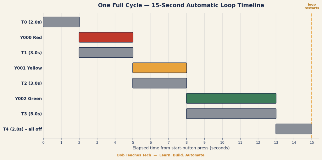
Figure 3. One full 15-second cycle of the automatic loop sequence
Industrial Applications
This exact timer-chain pattern, not just “timers in general,” but specifically cascaded on-delay timers with a self-resetting loop, shows up across a surprising range of real machines:
- Traffic light control: The exact pattern built here, cascaded on-delay timers driving lamp outputs, is the backbone of real intersection controllers, just with more phases and safety interlocks.
- Conveyor indexing: A timer holds a conveyor running for a fixed duration or dwell time between product transfers, then hands off to the next stage automatically.
- Bottle/can filling machines: Fill time is frequently timer-controlled: the valve opens, the timer counts the fill duration, the valve closes, and the sequence advances to capping.
- Packaging line sequencing: Wrap, seal, and cool stages on a packaging line often run as a timed loop, each stage holding for a preset duration before releasing to the next.
- Wash-down and CIP cycles: Clean-in-place systems for food and beverage equipment use timed loops for pre-rinse, wash, and sanitize stages, repeating for a set number of cycles.
- Pedestrian crossing signals: A close cousin of this exact project, a timer sequence controlling walk/don’t-walk phases, often synchronized with the vehicle traffic lights.
- Parking garage lighting: Timer loops control lighting zones on delay-off timers, dimming or shutting sections down after a preset idle period.
- Irrigation systems: Agricultural and landscape irrigation controllers cycle through zones on fixed timers, looping through the full watering schedule daily.
- Batch mixing processes: Mixing, dosing, and settling stages in batch chemical or food processes are frequently sequenced by timers rather than sensors, especially for consistent recipes.
- Automated car wash sequences: Soap, rinse, wax, and dry stages typically run on a timed sequence loop, sometimes with sensor overrides for vehicle position.
- Elevator door timing: Door-open dwell time, close delay, and re-open-on-obstruction logic all rely on the same timer-cascade thinking.
- HVAC damper sequencing: Staged damper and fan startup sequences use timed delays to avoid inrush current spikes from starting every motor simultaneously.
- Warning light and buzzer patterns: Flashing beacon patterns, pre-start warning horns, and staged alarm escalation all use timer loops to create repeating patterns.
- Bottling/canning line changeover indicators: Status tower lights cycling through colors to indicate machine state (running, changeover, fault) often reuse this exact red/yellow/green timer pattern.
- Automated greenhouse ventilation: Vent and fan cycles that open, hold, and close on a repeating timed schedule to regulate temperature without constant sensor polling.
Common Mistakes Beginners Make
Most of these mistakes will happen to you at least once, and that’s normal. The key is to recognize them quickly.
1. Forgetting the seal-in contact on the start relay: Without it, the sequence only runs while the button is physically held, a classic first mistake.
2. Wiring the input as sinking when the PLC expects sourcing (or vice versa): The button appears to do nothing, even though continuity checks fine with a multimeter.
3. Mixing up X and Y addressing: Especially under time pressure, it’s easy to reference an output address where an input was intended.
4. Using decimal timer presets by mistake: FX-series 100ms timers use K-values in tenths of a second; K20 is 2.0 seconds, not 20 seconds.
5. Forgetting to clear PLC memory before downloading: Leftover rungs from a previous program can silently interact with new logic.
6. Downloading a program while the PLC is in RUN mode: This can cause partial or inconsistent program transfers on some FX CPUs.
7. Never converting the ladder before downloading: GX Works2 will block the download, but beginners often assume a syntax error is a communication problem instead.
8. Using a normally-open contact where a normally-closed one was needed: This single symbol flip is responsible for a huge share of “why won’t my lamp turn off” questions.
9. Not accounting for PLC scan time in fast sequences: Extremely short timer presets can behave inconsistently if they’re shorter than a few scan cycles.
10. Assuming all FX timers use the same time base: FX3U has multiple timer ranges (100ms, 10ms, and 1ms) depending on the device number; mixing them up produces wildly wrong durations.
11. Skipping the seal-in and using a maintained switch instead: Works, but changes the machine’s behavior in ways operators won’t expect if they’re used to momentary start buttons.
12. Leaving old rungs commented but still wired to real outputs: Disabled logic that still drives a physical output is a safety hazard waiting to happen.
13. Not labeling devices with comments: A program with bare X0, M0, T0 addresses and no comments becomes unreadable within a month, even to the person who wrote it.
14. Forgetting the reset rung entirely: The sequence runs once, appears to work in testing, then “mysteriously” stops, because nothing ever resets the timer chain.
15. Resetting a timer that’s also being used to hold an output: Resetting T1 while its normally-closed contact is still driving Y000 can cause an output to flicker or drop unexpectedly.
16. Ignoring lamp voltage ratings: Wiring a 24V-rated stack light to an AC output module (or vice versa) can damage the lamp assembly.
17. Not isolating power before wiring: Working on mains-connected terminals live is one of the most common causes of injury on a training bench.
18. Overloading a single output point: PLC output points have current limits; driving a high-draw lamp directly can shorten the output’s life or damage it outright.
19. Confusing GX Works2 and GX Works3: GX Works3 doesn’t natively support FX3U project files the same way – beginners sometimes download the wrong software entirely.
20. Not testing inputs independently before writing logic: Skipping the “press the button and watch X0 change state” check means wiring problems get misdiagnosed as programming problems.
21. Assuming the loop will “just know” to stop after one cycle for testing: Without a temporary stop condition, debugging a fast-looping sequence on a live panel can be genuinely disorienting.
22. Using the same timer number twice in one program: FX CPUs won’t stop you from double-using a timer address, and the resulting conflict can be very hard to spot in the ladder view.
Troubleshooting Guide
| Symptom | Possible Cause | Solution |
| X0 never changes state when SB1 is pressed | Sourcing/sinking mismatch, broken wire, or a bad common connection | Check X0 in the PLC’s I/O monitor while pressing the button; verify S/S terminal wiring matches your input mode |
| M0 won’t stay on after releasing the button | Missing or miswired seal-in contact on rung 0 | Confirm the OR M0 branch is wired in parallel with X0, not in series |
| Red lamp never turns on | Y000 rung miswired, or T1’s contact used as normally-open instead of normally-closed | Re-check rung 3’s contact types against the walkthrough |
| Lamps light but never change colour | Timer preset (K-value) missing or set to zero | Open each timer coil and confirm the K-value matches the intended preset |
| Sequence runs once, then stops permanently | Missing reset rung (rung 9), or T4 never wired | Confirm T4’s contact resets T0 through T3 |
| Sequence loops far faster or slower than expected | Wrong timer time-base device number used, or K-value entered as seconds instead of tenths | Double-check you’re using standard 100ms timers (T0–T199 on most FX3U configurations) and K-values in tenths of a second |
| Program won’t download | PLC left in RUN mode, wrong COM port selected, or ladder not converted | Switch to STOP, reselect the COM port under Transfer Setup, and run Convert All before retrying |
| Everything works in Monitor Mode but not on power-up | Program wasn’t actually written to the PLC’s non-volatile memory, or PLC was left in STOP after download | Re-download and confirm RUN mode after cycling power |
Best Practices
- Add a plain-language comment to every device (X, Y, M, T). Your future self will thank you.
- Group related rungs together and use rung comments to mark logical sections of the program.
- Keep a consistent addressing convention across projects so you’re not relearning your own habits each time.
- Test inputs and outputs independently (forced I/O) before trusting them inside more complex logic.
- Build in a manual stop condition during development, even if the production sequence won’t have one yet.
- Avoid double-coiling the same output in more than one rung – it’s legal in some CPUs but a common source of confusing behavior.
- Back up your program (both the GX Works2 project file and a PLC-read-back copy) before making major changes.
- Document your timer chain’s total cycle time somewhere in the project notes – it saves recalculating it by hand later.
Safety Considerations
This project uses mains voltage on the power supply’s input side. Always isolate and lock out the circuit before wiring or making changes, and never work on live terminals.
Confirm your power supply, PLC, and stack light are all rated for the voltages you’re actually applying – mismatched ratings are a fire and equipment-damage risk, not just a “it won’t work” inconvenience.
In any real (non-training) automation system, a timer-only sequence should never be the sole safety mechanism for anything involving moving machinery, pressure, or heat. Timers control timing – they don’t sense hazards. Real machines pair sequences like this with E-stops, guards, and safety-rated interlocks.
If you’re adapting this project for a classroom or training lab, make sure learners understand the difference between this low-voltage demo and a live industrial panel before they work on anything beyond a training kit.
Performance Optimization
This sequence is simple enough that PLC scan time is not a concern. Five timers and a few contacts execute in less than a millisecond per scan on an FX3U.
As sequences grow larger (dozens of steps, multiple parallel branches), keep an eye on total program size and avoid deeply nested contact structures where a simpler internal-relay-driven state flag would be clearer and faster to scan.
If you eventually convert this pattern into a step-sequencer using STL (Sequential Function Chart-style) programming, you’ll often get both better performance and better readability for sequences longer than six or seven steps.
Future Improvements
Emergency stop – Add a normally-closed E-stop contact in series with the seal-in rung so any stop condition immediately drops M0 and halts the sequence.
Pedestrian crossing phase – Add a second input and a parallel timer branch that inserts a walk phase, matching real intersection logic.
Night mode / flashing amber – Add a mode-select input that bypasses the full sequence and instead flashes Y001 on a short timer, mimicking off-peak traffic signal behaviour.
HMI integration – Replace the physical stack light monitoring with an HMI screen showing live sequence status, elapsed time, and manual override controls.
SCADA reporting – Log cycle counts and run time to a SCADA historian for uptime tracking – useful even on a training project as practice for real reporting requirements.
Counter-based cycle limiting – Add a counter that increments each time the sequence loops, and stop automatically after a preset number of cycles – useful for demonstrations or test runs.
Analog sensor input – Replace a fixed timer with an analog light-level or traffic-density sensor to dynamically adjust green-phase duration.
Frequently Asked Questions
What is a PLC timer loop sequence?
It’s a program structure where a chain of timers advances a machine through a series of timed steps, then automatically restarts the chain once the last step finishes – creating a continuous, unattended repeating cycle.
What’s the difference between a PLC loop and a PLC program that just runs once?
A one-shot program executes its steps and then sits idle. A loop actively resets its own conditions at the end of the sequence so the steps run again without operator input.
Do I need an internal relay to build a timer loop?
Not strictly, but it’s good practice – a master relay like M0 gives you one clean place to add stop conditions, interlocks, or mode switches later without rewiring every rung.
What does K20 mean on an FX3U timer?
K is the preset value prefix, and for a standard 100ms timer, the number represents tenths of a second – K20 equals 2.0 seconds.
Can I use a different timer preset for each lamp?
Yes – each timer in this sequence has its own independent preset, so you can make each phase as short or long as you like.
Why does the sequence use five timers instead of three?
Three timers would control the three lamp durations, but two more (T3 and T4 in this build) are needed to hold the green phase for its own duration and to create the reset/loop-back gap.
What happens if I only use three timers and skip the reset logic?
The sequence runs exactly once – red, yellow, green – and then stops, because nothing resets the timer chain back to the start.
Is GX Works2 or GX Works3 correct for FX3U?
GX Works2 is the standard programming software for the FX3U family. GX Works3 primarily targets Mitsubishi’s newer iQ-F and iQ-R CPU families.
Why do I need to clear PLC memory before downloading a new program?
It removes any leftover logic and device values from a previous program, preventing old rungs from silently interacting with your new ones.
Can this sequence run without a start button, on power-up automatically?
Yes – you’d replace the X0 contact with a special “initial pulse” or always-on device, though keeping a manual start is usually safer for testing.
What’s the difference between sourcing and sinking inputs?
It describes which side of the input circuit supplies positive voltage. In sinking wiring, the PLC supplies positive and the field device switches common; in sourcing wiring, it’s reversed.
Why is my push button not registering on the input monitor?
The most common causes are a sourcing/sinking mismatch, a loose common wire, or a faulty contact block – verify with the I/O monitor while pressing the button.
What is a normally closed contact used for in this program?
It’s used to hold an output on until a timer finishes, at which point the contact opens and automatically switches the output off – no extra “turn off” rung required.
How long is one full cycle of this sequence?
With the presets used in this walkthrough, one full cycle takes 15 seconds: 2s startup, 3s red, 3s yellow, 5s green, and a 2s all-off gap before restarting.
Can I add more lamps or steps to this sequence?
Yes – extend the same pattern: each new step needs its own timer, an output rung holding while the current timer is done and the next timer isn’t, and a rung starting the next timer.
What’s the purpose of the seal-in contact on M0?
It lets M0 stay energised after you release the momentary start button, keeping the sequence running for its full cycle instead of only while the button is held.
Is this the same logic real traffic light controllers use?
The core concept – cascaded timers driving lamp phases with an automatic loop-back – is the same, though real controllers add many more safety interlocks, phases, and often sensor-based adjustments.
Can a counter replace a timer in this sequence?
For duration-based steps like lamp timing, no – counters respond to events, not elapsed time. Counters are better suited to tracking how many full cycles have run.
What’s the risk of not adding an E-stop to a real version of this circuit?
Without an emergency stop, there’s no fast, reliable way to halt the sequence if something goes wrong – unacceptable on any real machine, even though it’s a reasonable omission on a low-voltage training demo.
Why does my lamp flicker instead of turning on solidly?
This is usually a wiring or power supply issue (loose common, undersized power supply) rather than a logic issue, since ladder outputs are stable once energised.
Can I build this same sequence on an Allen-Bradley or Siemens PLC?
Yes – the underlying pattern (cascaded on-delay timers driving outputs, with a final timer resetting the chain) is portable to any PLC platform, though instruction names and addressing will differ.
What does RST do in Mitsubishi FX ladder logic?
RST resets a timer, counter, or bit device back to its initial (off/zero) state, which is what allows the timer chain in this project to restart automatically.
Why use ANI instead of AND in the instruction list?
ANI represents an AND with a normally-closed contact – it’s true when the referenced device is off, which is exactly the condition needed to hold an output until a timer completes.
How do I know if my FX3U timer is 100ms, 10ms, or 1ms?
It depends on the specific timer device number range configured for your CPU – check your FX3U’s programming manual or the device list in GX Works2 for the exact ranges available.
Can this project be simulated without physical PLC hardware?
Yes – GX Works2 includes a built-in simulation function (GX Simulator) that lets you test ladder logic, including timers, without a physical PLC connected.
What’s the benefit of learning timer loops before learning counters?
Timer loops introduce sequencing and self-resetting logic in a simpler, more predictable context, which makes counter-based (event-driven) sequencing easier to grasp afterward.
Why does the article use K30 for the yellow timer when the video doesn’t specify it?
The video’s narration doesn’t give an exact preset for the yellow phase, so this article uses 3.0 seconds for symmetry with the red phase – feel free to adjust it to your own preference.
Is it bad practice to reuse timer numbers across different parts of a large program?
Yes – each timer number should be used by exactly one coil in the whole program; reusing one causes conflicting, hard-to-diagnose behaviour.
What’s the fastest way to debug a sequence that isn’t looping correctly?
Open a device monitor showing X0, M0, and T0–T4 simultaneously, then step through a real cycle while watching exactly which device fails to change state as expected.
Can I control the stack light lamps with relays instead of directly from PLC outputs?
Yes, and for lamps drawing more current than the PLC’s output rating, you should – use the PLC output to drive an interposing relay, and let the relay switch the lamp’s actual power.
What happens if two timers in the chain share the same K-value?
Nothing breaks – timers are independent devices, and identical presets are perfectly normal (as used here for T1 and T2).
Should beginners start with ladder logic or structured text?
For PLC platforms like the FX3U with strong ladder tooling and documentation, ladder logic is the more approachable starting point – it maps directly onto physical relay logic that’s easier to visualise.
How is a PLC loop sequence different from a PLC state machine?
A simple timer loop like this one always follows the same fixed path. A state machine can branch to different states based on conditions, making it more flexible but also more complex to design and debug.
What is the FX3U’s maximum number of timers?
This varies by memory configuration, but the FX3U supports hundreds of timer devices – far more than any single sequence like this one would need; check your specific CPU’s device list for exact limits.
Can I trigger an external buzzer using this same timer pattern?
Yes – treat the buzzer as another output, and either tap it off an existing timer’s contact or add a dedicated short timer pulse for an audible warning tone.
Watch, Download, and Keep Learning
Ready to see it running?
Watch the full build in the companion YouTube video. You can also download the ladder diagram, wiring diagram, and PLC program files below. Subscribe to Bob Teaches Tech to catch the next tutorial in this series.
Watch the video · Download the ladder diagram · Download the wiring diagram · Download the PLC program · Subscribe on YouTube · Explore related tutorials.
About The Author