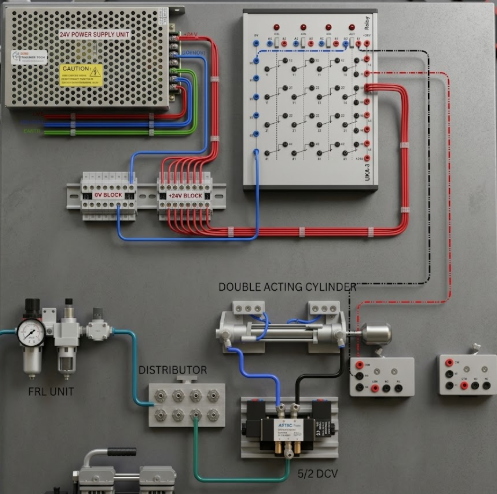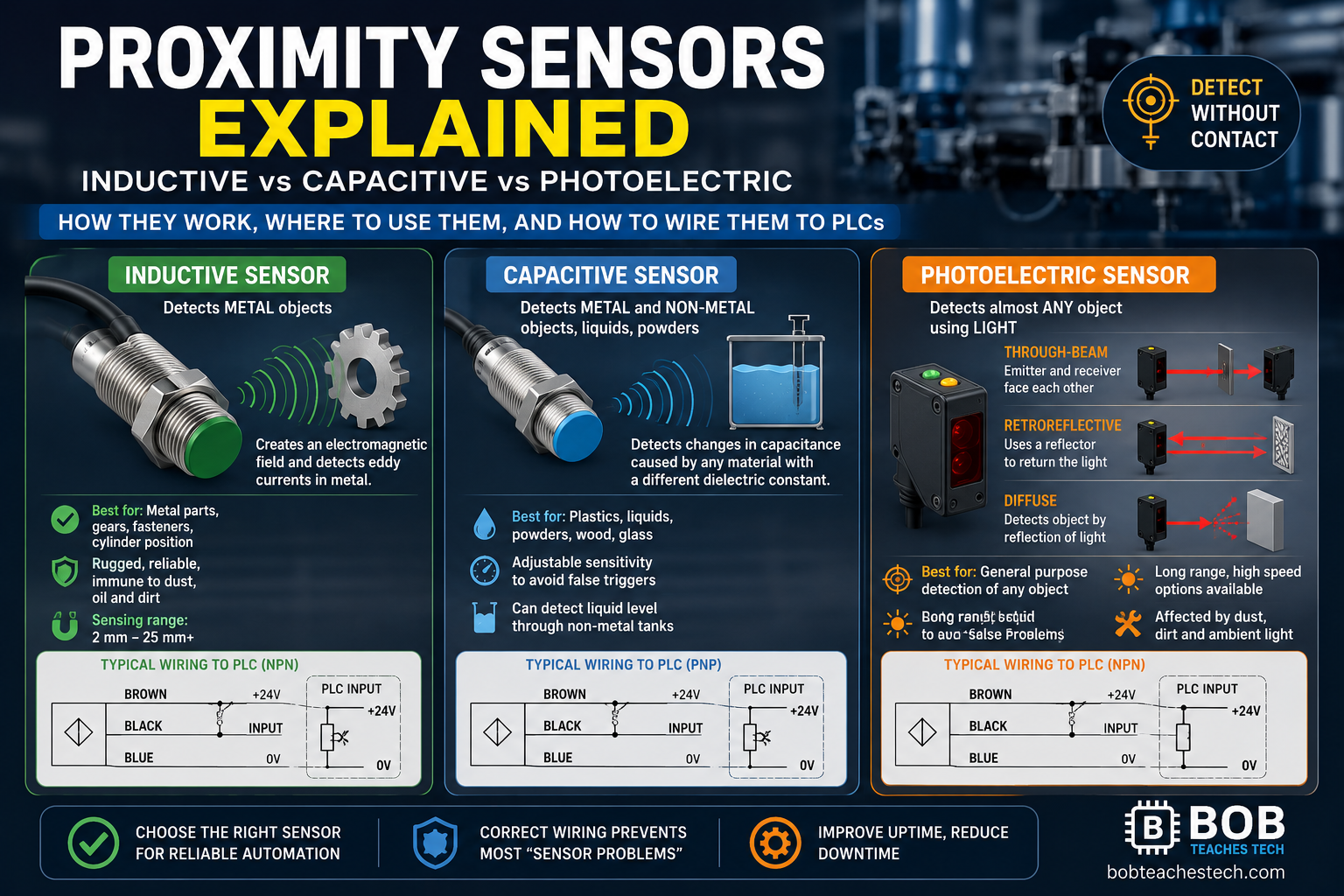

Photoelectric sensors are among the most widely used industrial sensors because they can detect objects without making physical contact. They are found in conveyor systems, packaging machines, bottle filling equipment, sorting systems, automatic doors, counting applications, and numerous other automation projects.
One challenge many technicians encounter is that most industrial photoelectric sensors operate on 24V DC, while many industrial timer relays operate using 110VAC or 220VAC.
Since these two circuits cannot be connected directly, an interposing relay is used to safely interface the low-voltage DC control circuit with the higher-voltage AC timer circuit.
In this tutorial, you’ll learn exactly how this wiring works, why each connection is made, and how the relay acts as the electrical bridge between the sensor and the timer.
By the end of this guide, you’ll understand not only how to build the circuit, but also how to troubleshoot it if it doesn’t work the first time.
Watch the Complete Video Tutorial
Before following the written guide, you can watch the complete wiring demonstration on YouTube.
▶ Video Tutorial: https://www.youtube.com/watch?v=9umvd7ogr4Q
The article below expands on the concepts shown in the video with additional explanations, diagrams, and troubleshooting tips.
Components Used
This project uses a combination of AC and DC control components.
| 24V DC Power Supply | Powers the photoelectric sensor and relay coil |
| Photoelectric Sensor | Detects objects |
| Finder Interposing Relay | Interfaces the sensor with the AC timer |
| Relay Socket | Makes wiring easier |
| AC Timer Relay | Provides adjustable delay |
| Terminal Blocks | Simplifies wiring |
| Indicator Lamp | Shows system status |
| AC Supply | Powers the timer |
| Wiring Conductors | Control connections |
Why an Interposing Relay is Necessary
Many beginners ask:
“Why can’t I connect the photoelectric sensor directly to the timer?”
The answer is simple.
A standard industrial photoelectric sensor typically provides a 24V DC transistor output, while the timer in this project requires an AC control voltage.
Connecting them directly can damage both devices.
Instead, the sensor energizes a 24V DC relay coil, and the relay contacts safely switch the AC circuit independently. This electrical isolation is a standard industrial practice.
Think of the relay as an electrically operated switch.
How the Circuit Works
The operation follows a straightforward sequence:
- The power supply generates 24V DC.
- The sensor receives power.
- The sensor detects an object.
- The sensor output energizes the relay coil.
- The relay changes state.
- The relay contact controls the AC timer.
- The timer begins timing.
- After the preset delay, the timer changes its contacts.
- The output can operate another device such as:
- Contactor
- Motor starter
- Solenoid valve
- Alarm
- Indicator lamp
Understanding the Wiring Step by Step
Step 1 – Connect the AC Power Supply
The first step is wiring the power supply.
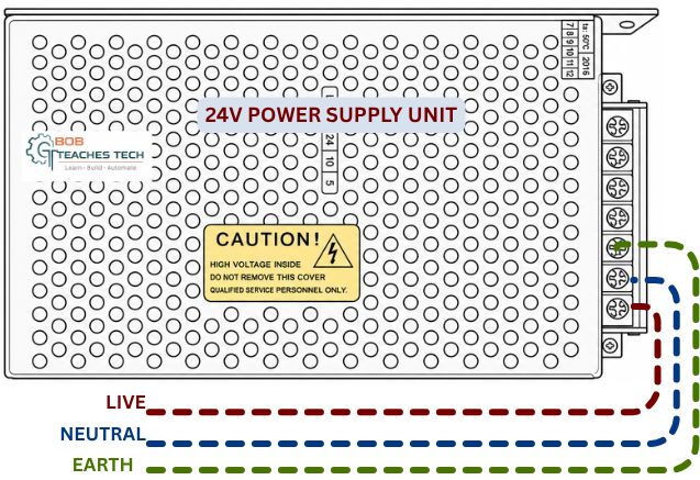
Connect:
- Live
- Neutral
- Earth
to the power supply input terminals.
This allows the supply to generate a stable 24V DC output for the control circuit.
Step 2 – Connect the 24V DC Output
The DC output is distributed through terminal blocks.
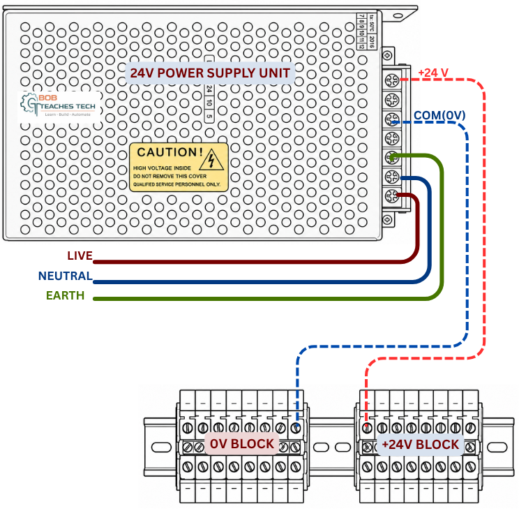
Advantages include:
- Easier troubleshooting
- Cleaner panel layout
- Faster maintenance
- Easy expansion
Separate terminal blocks are used for:
- +24V
- 0V
Step 3 – Power the Photoelectric Sensor
Most industrial 3-wire sensors follow this color code:
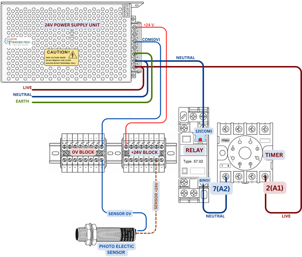
Brown → +24V
Blue/White → 0V
Black → Output Signal
Always verify the sensor datasheet because manufacturers can differ slightly, although this is the most common wiring convention.
Step 4 – Wire the Sensor Output
The black wire does not power the relay directly.
Instead, it acts as the switching output.
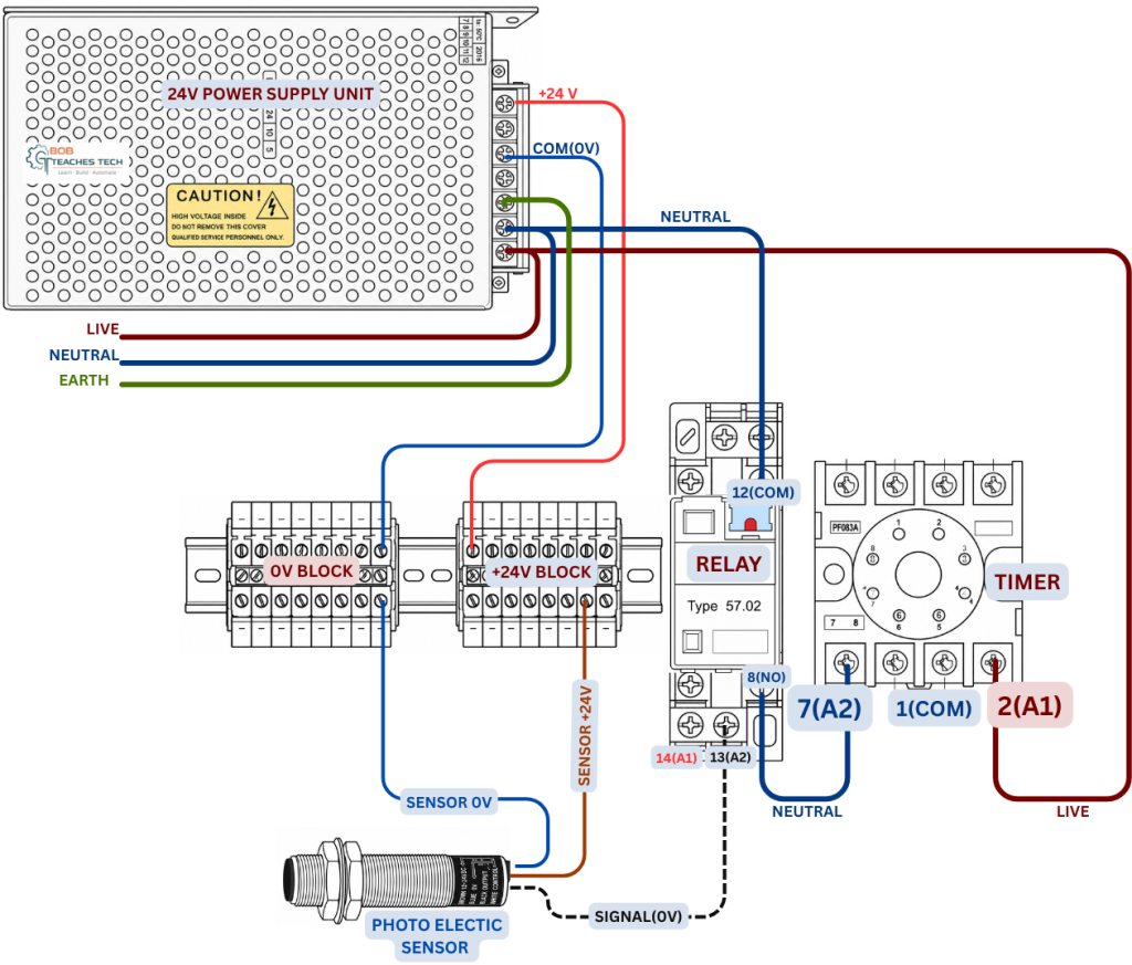
Depending on the sensor type, it may be:
- PNP (Sourcing)
- NPN (Sinking)
This project uses the sensor output to energize the relay coil.
Understanding whether your sensor is PNP or NPN is essential because the wiring differs.
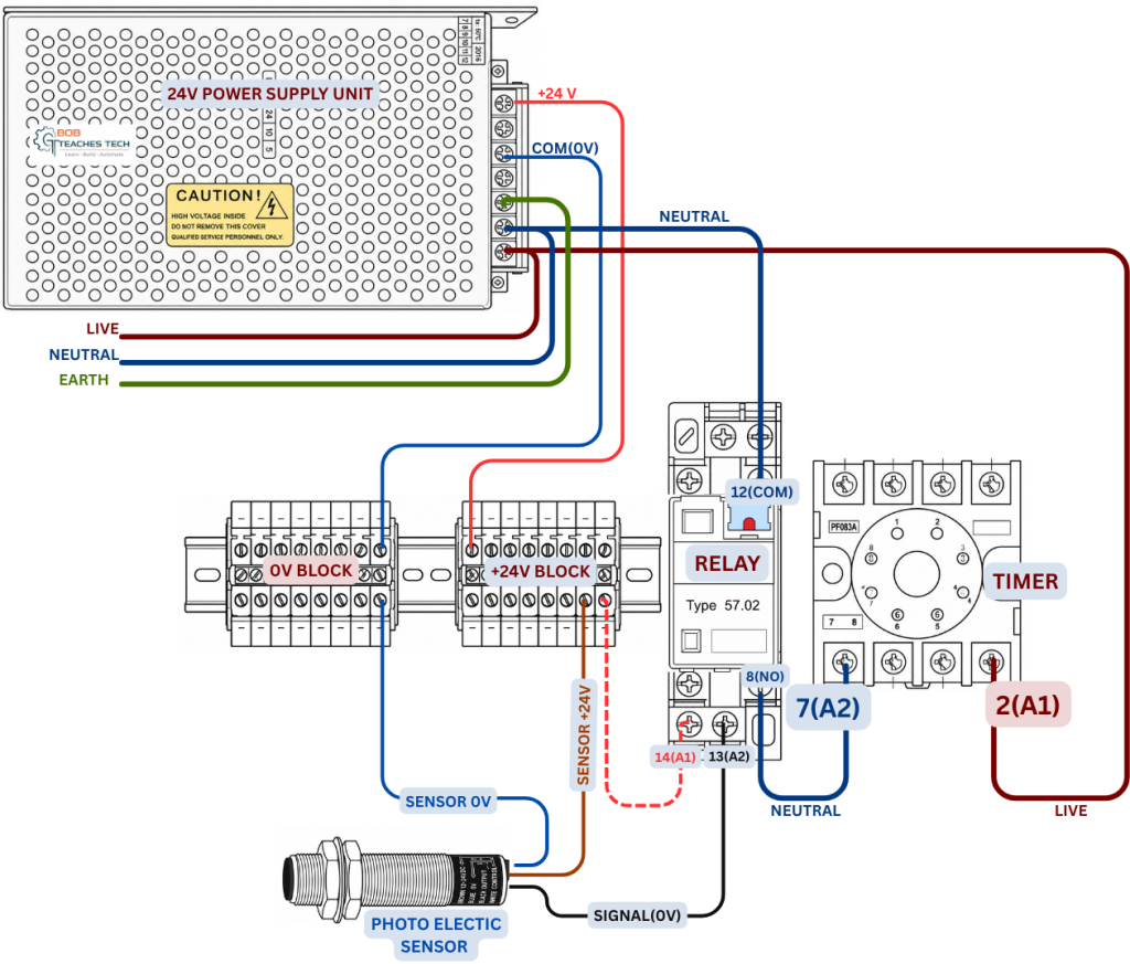
Step 5 – Connect the Relay Coil
The relay coil terminals are:
A1-14
A2-13
When the sensor activates, the relay coil energizes.
You should hear a distinct click.
That click tells you:
- The sensor works
- The relay is energized.
- The control circuit is operating.
Step 6 – Wire the Relay Contacts
Unlike the coil, relay contacts are electrically isolated.
Common terminals include:
- COM
- NO
- NC
This project uses the relay contacts to switch the AC timer input safely.
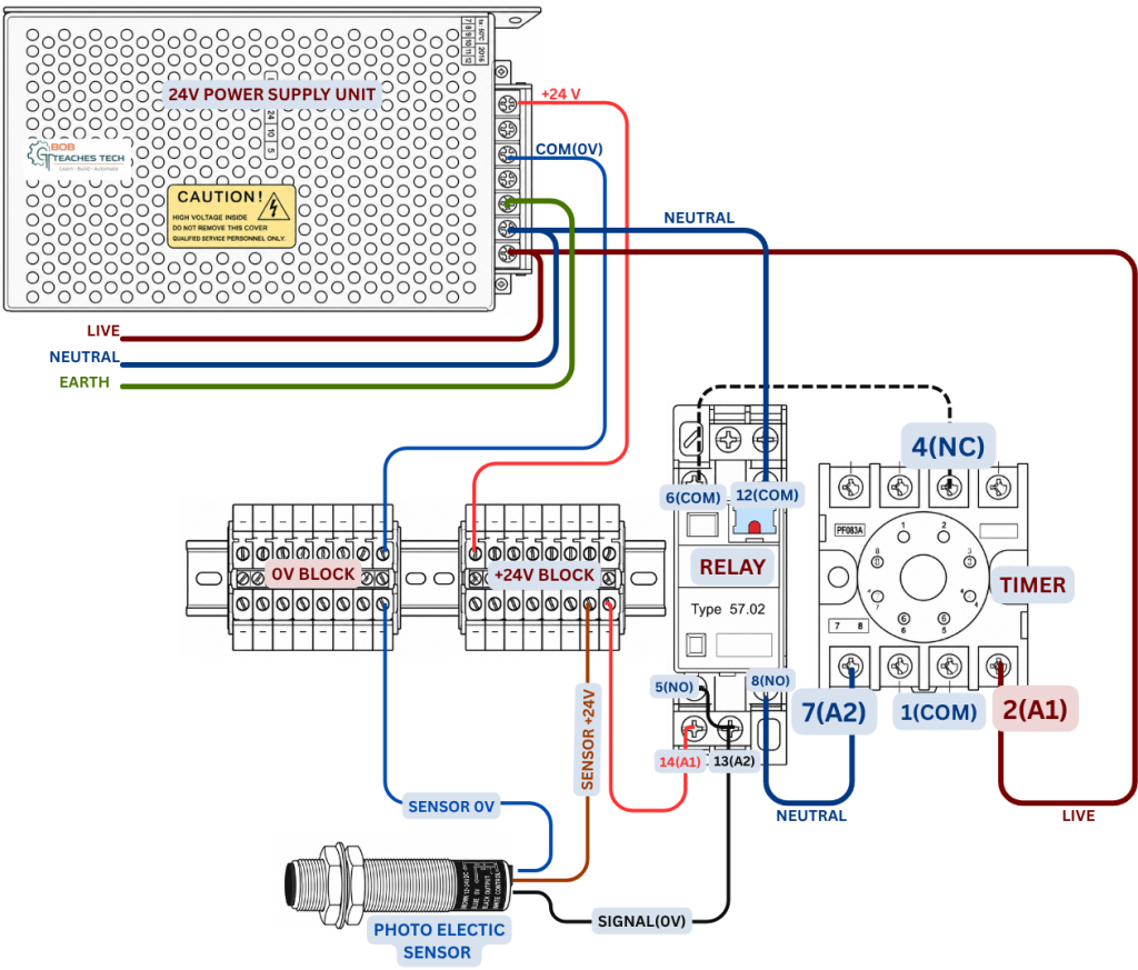
Because the contacts are isolated, the DC and AC circuits never directly connect.
Step 7 – Connect the Timer Normally Closed Contact
The timer requires:
The latched input flows through the normally closed contact of the timer routing to 0V.
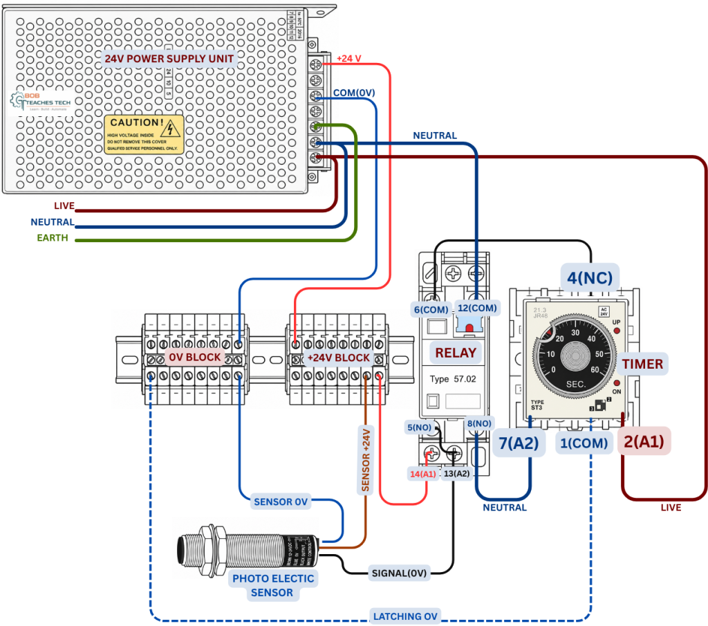
Once powered, the timer begins counting according to its preset delay.
Depending on the timer model, it may operate as:
- ON Delay
- OFF Delay
- Interval Timer
- One-shot Timer
Step 8 – Wire the Indicator Lamp
The indicator lamp provides a quick visual indication of circuit operation.

Benefits include:
- Faster troubleshooting
- Easy fault diagnosis
- Visual confirmation that the relay has energized
Practical Industrial Applications
This exact wiring method is commonly used in:
Conveyor Systems
Detect packages before starting conveyors.
Bottle Filling Machines
Delay filling after bottle detection.
Automatic Doors
Introduce opening or closing delays.
Product Counting
Generate timed counting pulses.
Packaging Machines
Coordinate sensors with pneumatic actuators.
Sorting Systems
Delay diverter cylinders.
Labeling Machines
Synchronize labels with product movement.
Common Wiring Mistakes
Reversing 24V Polarity
Always verify:
Brown → +24V
Blue → 0V
Mixing PNP and NPN Wiring
Using the wrong wiring method prevents the relay from energizing.
Always identify your sensor output type before installation.
Incorrect Timer Voltage
Never connect:
220VAC timer
to
24V DC
Always check the timer nameplate.
Wrong Relay Contact
Many beginners accidentally wire:
NC instead of NO
or vice versa.
Double-check the relay numbering before powering the circuit.
Troubleshooting Guide
Sensor LED Doesn’t Turn On
Check:
- 24V power
- Polarity
- Wiring
- Sensor alignment
Relay Doesn’t Click
Check:
- Sensor output
- Coil voltage
- Relay socket
- Coil continuity
Timer Doesn’t Start
Check:
- AC supply
- Relay contacts
- Timer voltage rating
Indicator Lamp Doesn’t Illuminate
Verify:
- Lamp voltage
- Neutral connection
- Output wiring
Safety Tips
Always:
- Verify voltage using a multimeter
- Use proper wire ferrules
- Label all terminals
- Ground the power supply enclosure
- Keep AC and DC wiring separated
- Use the correct fuse or circuit breaker
- Disconnect power before wiring
Frequently Asked Questions
Can I use a PLC instead of the relay?
Yes. If your PLC has compatible DC inputs and timer functions, the relay and standalone timer can often be replaced by PLC logic.
Can I use a PNP sensor?
Yes.
Simply modify the wiring according to the sensor’s output type. PNP sensors source positive voltage, while NPN sensors switch the negative side of the circuit.
Why use terminal blocks?
Terminal blocks improve organization, simplify maintenance, and make future modifications much easier.
Can I connect multiple sensors?
Yes.
Additional sensors can be wired using appropriate relay logic or PLC inputs depending on the application.
Interposing 24V DC Photoelectric Sensor with AC Timer Relay
By using an interposing relay, you can safely integrate a 24V DC photoelectric proximity sensor with an AC timer relay, creating a reliable and industry-standard control circuit. This approach provides electrical isolation between the sensor and the timer, simplifies troubleshooting, and makes the system easier to expand in the future.
Although this project is ideal for beginners learning industrial control wiring, the same design principles are used every day in conveyor systems, packaging machinery, bottling plants, material handling equipment, and factory automation panels around the world.
If you followed both the video tutorial and this guide, you should now understand not just how to wire the circuit, but also why each connection is made-a skill that will help you confidently build and troubleshoot many other industrial automation projects.
About The Author