With older PLCs, you could use any address as a bit, word, or register and figure out the details as you want. Now, modern tag-based platforms like Studio 5000, TIA Portal, and Mitsubishi GX Works3 make you choose a data type for every tag. The data type decides how much memory the tag uses, what values it can hold, and what happens if a value is too big or too small.
This is more important than it seems. If you choose the wrong data type, your program might not show an error. Instead, it could give you a value that looks right but is actually wrong, which can cause confusing problems later. This guide explains the main IEC 61131-3 data types you’ll use most: BOOL, integers, REAL, strings, arrays, and structures. You’ll learn enough about memory use and range limits to help you avoid these problems from the start.
Importance of Data Types in Modern Tag-Based PLCs
On older PLCs, a memory spot like N7:0 was just 16 bits, and you had to remember if you were using it as a signed integer, an unsigned counter, or a group of bits. Tag-based platforms remove this guesswork. When you create a tag, you pick its data type, and the software makes sure only the right kind of data and operations are allowed.
This change is a big step forward because the compiler can now catch mistakes that would have gone unnoticed before. However, it also brings a new kind of bug for those used to address-based programming. Type mismatches can still compile and run without warning, since the platform might convert values in a way that loses information. The best way to avoid these hidden problems is to know what each data type can and cannot store.
BOOL: The Single-Bit Data Type
BOOL is the simplest data type in any PLC. It’s a single bit that holds either 0 (false) or 1 (true). Every digital input, output, and internal flag, such as a run permissive, fault latch, or done bit from a timer or counter, is a BOOL. Even though it only needs one bit, most platforms pad BOOL tags to a full byte or word for easier addressing and better performance. This is good to remember if you ever need to estimate your program’s total memory use.
- Typical uses: digital I/O, start/stop permissives, alarm and fault flags, done/enable bits from timers and counters.
- Range: 0 or 1 (FALSE or TRUE). No other values are possible.
- Common mistake: treating a BOOL like a numeric flag and trying to store something other than 0 or 1 in it. Most platforms will either reject this or quietly convert it to a boolean value.
Integer Types: INT, DINT, and Overflow Risk
Integer types store whole numbers without decimals. They come in three common sizes, and choosing the wrong size is the most common data-type mistake in PLC programming. Overflow errors don’t give any warning.
- SINT (short integer / byte): 8 bits, range -128 to 127. Rarely used directly for process values; more common for small status codes or byte-level communication data.
- INT (integer / word): 16 bits, range -32,768 to 32,767. The default choice for most counter accumulators, simple analog raw values, and small process quantities.
- DINT (double integer / double word): 32 bits, range about -2.1 billion to 2.1 billion. Use this for large counts, high-resolution encoder positions, or any value that could go over 32,767 during a production run.
Overflow is the main risk when choosing an integer type. If an INT tag with 32,767 is increased by one, there won’t be an error. Instead, it wraps around to -32,768. A production counter that suddenly becomes a large negative number is a classic, hard-to-find problem. That’s why lifetime part counts, total run-hours, and anything else that adds up over time should use DINT instead of INT, even if the current value is small.
KEY CONCEPT
Overflow happens quietly. A PLC won’t warn you when an integer tag goes past its range. Instead, it wraps around using standard two’s-complement math, which gives a number that looks valid but doesn’t make sense for your process. Always choose integer tag sizes based on the largest value they might reach, not just what you expect at first.
REAL (Floating Point) and When You Need It
REAL is a 32-bit floating-point type. Use it when you need a value with a fractional part, like temperatures, pressures, flow rates, scaled analog values, PID gains, or anything measured in engineering units instead of raw counts. REAL gives about seven significant decimal digits of precision over a huge range (about ±3.4 × 10^38), which is more than enough for almost any process variable.
The downside is that REAL math is slower than integer math on many PLCs. Floating-point values also have a subtle risk: two REAL values that should be equal might differ slightly in the last decimal place because of rounding. This makes direct equality checks, such as Temp_C = 50.0, unreliable. Instead, compare against a small range, for example, ABS(Temp_C – 50.0) < 0.01, when you need to test if a floating-point value is equal.
- Use REAL for: engineering-unit process values, scaling formulas, PID parameters, any calculation involving division that isn’t guaranteed to produce a whole number.
- Don’t use REAL for simple counts, bit flags, or array indices. Use BOOL, INT, or DINT for these instead. Using REAL in these cases just wastes memory and processing time without any benefit.
Strings and Timers as Data Types
Two data types don’t fit neatly into the numeric hierarchy above but appear constantly in real programs: STRING and the built-in TIMER type.
- STRING stores text, such as batch IDs, operator names, recipe names, or alarm messages. Most platforms set STRING to a fixed maximum length when you create the tag. For example, STRING[16] is used for a 16-character batch ID, and there is a length field that tracks how much space is used. If you make a string too short, any extra text is quietly cut off. This is another example of a data-type mismatch that fails silently instead of showing an error.
- TIMER is a special data type on tag-based platforms. A timer instruction (TON, TOF, RTO) uses its own structure-like data type, which includes member values like .ACC (accumulated time), .PRE (preset time), and a .DN (done) bit. This is similar to the user-defined types (UDTs) discussed later. Thinking of a timer as a small built-in structure can make user-defined structures easier to understand when you get to them.
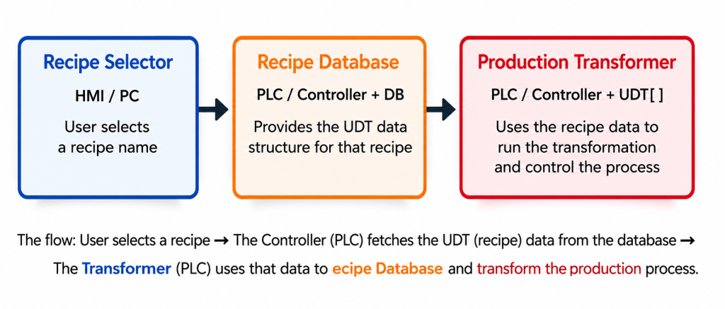
Arrays Explained with a Recipe Example
An array is an ordered list of values with the same data type, accessed by a number. Arrays are helpful when you have many of the same kind of value, like ten ingredient weights in a recipe, sixteen zone temperatures in an oven, or thirty-two digital inputs on an expansion card. They let you loop over these values in your program instead of repeating the same logic.
Imagine a recipe with ten ingredients, each needing a weight in kilograms. You could declare ten separate REAL tags (Ingredient1, Ingredient2, … Ingredient10), but this makes it hard to process all ingredients together, such as summing them, checking each against a tolerance, or logging them to a batch record. It’s tedious and easy to make mistakes. Instead, you can declare an array as Ingredients : ARRAY[0..9] OF REAL, which stores all ten values under one name. You can then access them as Ingredients[0] through Ingredients[9], and use a single FOR loop or indexed ladder rung to process all ten at once. Arrays are also useful for handling multiple sensors of the same type, ingredient lists, zone temperatures, or storing historical values, like the last 60 seconds of a reading with one value per second.
- Arrays are not good for grouping values of different types that describe one thing. For that, you should use a structure (UDT), which is explained next.
User-Defined Types (UDTs) / Structures Explained
A structure, called a User-Defined Type (UDT) on Allen-Bradley platforms and a Type or Struct on Siemens and Mitsubishi platforms, groups several related values of different data types under one tag name. Each value is accessed by its member name. While an array holds many values of the same type, a structure holds different values that all describe one logical thing.
A batch recipe is a good example. A single batch record usually has a text identifier, a target temperature, a mix duration, an array of ingredient weights, and a completion flag. These are five different data types that describe one real-world concept. If you define a UDT once and create tags of that UDT for each batch, every batch record will have the same structure, member names, and rules about what data it contains.
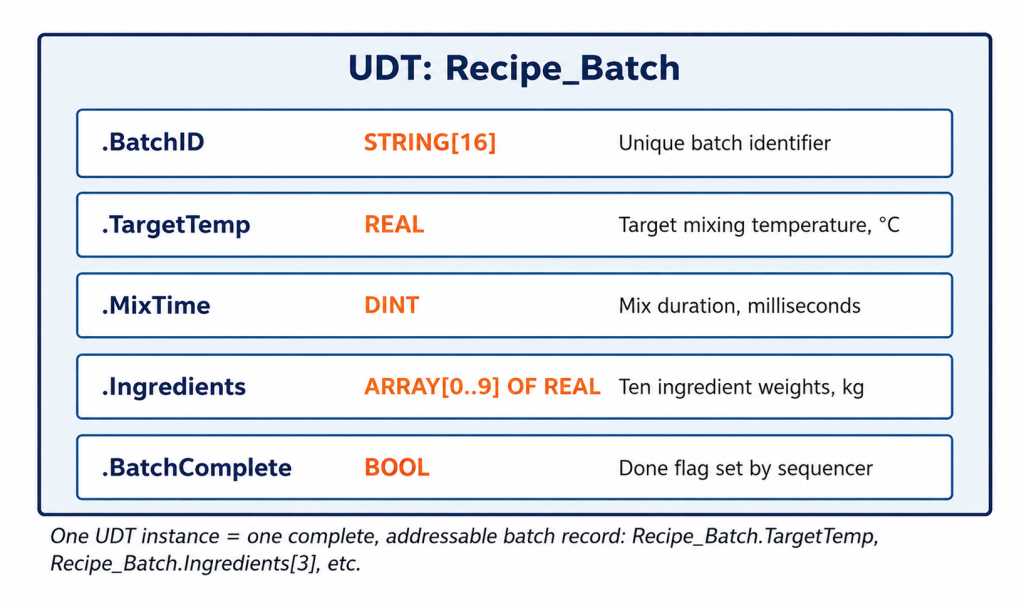
A UDT groups related values of different types under one tag. Each member is accessed by name, for example, Recipe_Batch.TargetTemp.
Once you have created this UDT, you can make as many Recipe_Batch tags as you need. You might have one for each active batch, one for each recipe template, or an array for a full production schedule. Each tag will have the same five members with the same data types. This is the same pattern used by built-in structures like TIMER with .ACC, .PRE, and .DN, and COUNTER with .ACC, .PRE, and .DN. UDTs let you create your own version of this pattern for your process data.
WHY THIS IS IMPORTANT FOR SCADA
Structures also make PLC-to-SCADA communication easier. Instead of mapping five separate tags into a SCADA system and hoping their names match, a single UDT tag includes all five members in one consistent structure. Most SCADA platforms can browse and connect to these automatically.
Worked Example: A Temperature Scaling Bug
Here’s a bug pattern that shows up on almost every vendor platform. It’s not a syntax error, but a data-type mismatch that gives a result that looks correct but is actually wrong. For example, a 4-20mA temperature transmitter sends a signal to an analog input card, which reports a raw ADC value from 0 to 16383 (14-bit resolution). The scaling formula then converts this raw value into a real-world temperature in degrees Celsius using a simple linear equation.
The scaling formula is mathematically correct. The problem is that the destination tag was declared as INT instead of REAL, so every result is quietly cut off at the decimal point.
The scaling formula is correct: Temp_C := (Raw_Cnt / 16383.0) * 200.0 – 50.0, which maps the raw 0-16383 range to a -50°C to 150°C process range. The bug is in how the destination tag, Temp_C, was declared. If Temp_C is set as INT instead of REAL, the platform silently cuts off the decimal part of the result on every scan. It does not round, so 49.9°C becomes 49, not 50.
By itself, a one-degree truncation might not matter for a rough process display. But this bug gets much worse if the truncated INT value is used in more calculations, like a PID loop, an alarm threshold, or a data-logging routine that needs REAL precision. The rounding error can add up and cause real control problems. The solution is to declare Temp_C (and every tag in the scaling formula) as REAL from the start, and only convert to INT at the final step if you really need an integer, such as when writing to a Modbus register that only supports integers.
- Root cause: destination tag declared as INT when the calculation producing its value is inherently floating-point.
- Symptom: values that are close to correct but consistently off by a fraction of a degree, or an alarm that trips a scan or two later than it should because of accumulated truncation.
- Fix: declare every tag carrying a scaled engineering-unit value as REAL, and convert to INT only where an integer is actually needed later, such as for a fixed-point Modbus register.
Vendor Comparison: Studio 5000 vs TIA Portal vs GX Works3
The IEC 61131-3 standard defines the underlying data type concepts consistently, but each platform’s naming and default tag behavior differs enough to cause confusion when moving between them.
| Concept | Studio 5000 (Rockwell) | TIA Portal (Siemens) | GX Works3 (Mitsubishi) |
| Single bit | BOOL | Bool | Bit (X/Y/M) or Bool_ label |
| 16-bit integer | INT | Int (16-bit) / Word (unsigned) | Word [signed] / Int |
| 32-bit integer | DINT | DInt (32-bit) / DWord (unsigned) | Double Word [signed] / DInt |
| Floating point | REAL | Real | Float (single precision) |
| Text | STRING | String[n] | String[n] |
| User-defined structure | UDT (User-Defined Type) | Type (PLC data type) / UDT | Structure (label-based) |
| Array declaration | Tag[0..9] via dimension property | Array[0..9] of ‹type› | Array[0..9] of ‹type› |
Table 1. Data type terminology across the three most common platforms.
There is a common trap when switching between platforms. Siemens’ Word and DWord types are unsigned by default, but Rockwell’s INT and DINT are always signed. A raw value that is a large positive number on a Siemens Word tag can be misread as a negative number if you copy it into a Rockwell INT tag without adjusting for the sign difference. This is another example of a silent data conversion bug that only becomes obvious when the numbers seem wrong.
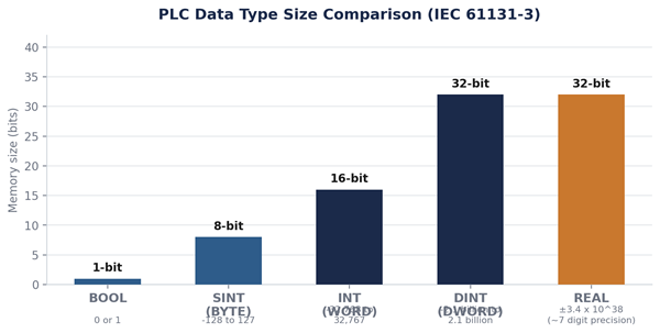
Table 2. Data type size and range comparison. This is the main reference for this article.
FAQ: PLC Data Type Questions Answered
What is the difference between INT and DINT in PLC?
INT is a 16-bit signed integer with a range of -32,768 to 32,767, while DINT is a 32-bit signed integer with a range of about ±2.1 billion. Use DINT for any value, like a lifetime counter or high-resolution position, that could go beyond INT’s range over time.
When should I use a REAL data type in a PLC?
Use REAL whenever a value has a real fractional part, like temperatures, pressures, flow rates, scaled analog values, and PID parameters. Avoid REAL for simple counts or array indices, where an integer type is faster and uses less memory.
What is a UDT in PLC programming?
A UDT (User-Defined Type), called a Type on Siemens platforms, is a structure that groups several related values of different data types, such as a batch ID, a target temperature, and a done flag, under one tag name. Each value is accessed as a named member.
Why did my PLC calculation give a slightly wrong number?
This is almost always a data-type mismatch, most often a REAL calculation result being assigned to an INT destination tag. This quietly cuts off the decimal part every scan instead of rounding it or showing an error.
What is the difference between an array and a structure in a PLC?
An array holds multiple values of the same data type, accessed by numeric index. This is useful for repeated items like ten ingredient weights. A structure (UDT) holds several values of different data types that describe one logical thing, and you access them by member name.
Where to Go Next
Data types are the foundation for everything else in tag-based PLC programming. Once you understand BOOL, integers, REAL, arrays, and structures, you’re ready to move into structured text, where you use these same data types with familiar programming syntax. You can also handle analog input scaling, which is a general version of the temperature-scaling bug example above, and can be used for any 4-20mA or 0-10V signal.
- Up next: Structured Text Programming for PLCs: A Practical Introduction
- Up next: Analog Input Scaling in PLC Programs