
At some point, every Modbus project faces the same confusion: a datasheet mentions “register 800,” a PLC program looks for a coil, and a SCADA tag returns bad data or a communication error. Usually, this happens because someone confused Modbus’s four register types or used the wrong function code. The good news is that there are some straightforward troubleshooting steps you can follow to quickly get things back on track-these are outlined just ahead to help you solve these common problems efficiently.
Quick Troubleshooting Checklist for Register Type or Function Code Errors:
– Double-check if the register is defined as a coil, discrete input, holding register, or input register in the device documentation.
– Make sure you are using the correct function code for the register type.
– Confirm whether the register number is using the legacy prefix system or is a protocol address (0-based or 1-based).
– If a read returns an error, try reading the same address with a different function code or check for off-by-one addressing.
– Validate the value against physical reality to spot scaling or mapping mistakes.
This checklist can save time in the field when register addressing or function codes don’t behave as expected. For example, using this approach recently helped one engineer quickly identify that a “bad data” error was caused by a mismatched function code for a pressure sensor, getting a system back online in minutes.
This confusion isn’t just for beginners. It happens during recommissioning, when integrating third-party devices, and even in vendor documentation that hasn’t been tested in real RS-485 networks. This guide explains all four register types, the old 0x/1x/3x/4x addressing convention, the function codes for each type, and includes a real troubleshooting example about a chiller controller where “register 800” means different things in different manuals.
The Four Modbus Register Types at a Glance
Modbus sorts all device data into four types. Two are single-bit (Boolean) values, and two are 16-bit words. In each pair, one type is read/write and the other is read-only. Knowing this simple 2×2 grid helps you avoid confusion.
| Register Type | Bit Width | Access | Legacy Address Range | Function Code(s) |
| Coil | 1-bit | Read/Write | 0x (00001–09999) | 01, 05, 15 |
| Discrete Input | 1-bit | Read-only | 1x (10001–19999) | 02 |
| Input Register | 16-bit | Read-only | 3x (30001–39999) | 04 |
| Holding Register | 16-bit | Read/Write | 4x (40001–49999) | 03, 06, 16 |
Here’s a helpful tip: bit-wide data shows a physical on/off state, like a valve, relay, or limit switch. Word-wide data covers measured or set values, such as temperature, setpoints, or counters. The second key point is whether you can write back to the device. Many integrators get this wrong, especially since vendors often put read-only data in Holding Registers for convenience instead of Input Registers, which can cause confusion. If you are unsure whether a register is truly writable or read-only, try sending a write command to that register in a safe test environment. If the operation fails or returns an error, it is likely read-only. Just be careful to avoid writing to critical values on a live system during this test.
Coils: Single-Bit, Read/Write
A coil is a single binary value that the master can read and write. Coils let Modbus control physical outputs, like starting a motor, opening a valve, turning on a relay, or acknowledging an alarm. Since coils are read/write, they are the only Modbus data type where the master can actually change the device’s state instead of just reading it.
Coils use the legacy 0x address range (00001–09999, or sometimes 000001–065536 in six digits). You read coils with Function Code 01 and write them with Function Code 05 for single bits, or Function Code 15 (0x0F) for multiple bits. In responses, coils are packed eight per byte, with the lowest bit for the lowest-numbered coil. This detail often causes problems for custom drivers, but most SCADA software handles it automatically.
Discrete Inputs: Single-Bit, Read-Only
A discrete input is also a single binary value, but the master can only read it, not write it. Discrete inputs are used to show the real-world state of things like limit switches, alarms, door interlocks, or run/stop feedback from a motor starter. Since the device controls these states, writing to them wouldn’t make sense and could be unsafe.
Discrete inputs use the legacy 1x range (10001–19999) and are only read with Function Code 02. Many budget devices skip this type and put digital input status in holding registers instead, to avoid extra firmware work. If you don’t see Function Code 02 in the documentation, the “digital inputs” are probably shown as coils or holding register bits, so always double-check before assuming the standard mapping.
Holding Registers: 16-Bit, Read/Write
A holding register is a 16-bit word that the master can read and write. It’s Modbus’s general-purpose data type, used for things that aren’t just on or off, like setpoints, PID gains, configuration settings, alarm limits, and recipe values. In practice, vendors often put read-only data here instead of in input registers.
Holding registers use the legacy 4x range (40001–49999) and work with three function codes: 03 for reading, 06 for writing a single register, and 16 (0x10) for writing multiple registers at once. Since Function Code 03 is widely supported and holding registers can store almost anything, manufacturers often use them for all kinds of data. That’s why just seeing a “4x register” label doesn’t tell you if the value is really meant to be writable or just happens to be in a writable spot.
Input Registers: 16-Bit, Read-Only
An input register is a 16-bit read-only word, like the discrete input but for larger values. It’s usually used for sensor readings such as temperature, pressure, flow, energy use, RPM, or any analog value the device measures but the master shouldn’t change. Input registers use the legacy 3x range (30001–39999) and are only read with Function Code 04.
In practice, input registers are the least-used of the four types. This isn’t because read-only data is rare, but because many manufacturers put that data in holding registers so masters that only use Function Code 03 can still read it. This shortcut makes things easier for vendors, but it means you can’t assume a “3x register” in a datasheet will always work with Function Code 04. The example later in this article demonstrates how this mismatch between register type and function code can cause confusion when the same register number is assigned to different data tables by different vendors, leading to frustrating troubleshooting situations. Watch for how this scenario unfolds in the practical chiller controller troubleshooting walk-through.
Function Codes Mapped to Each Register Type
The function code is the instruction sent in the Modbus request PDU (Protocol Data Unit). It’s the function code, not the register’s legacy address prefix, that tells the device which data table to use. If you send the wrong function code for an address, you won’t get the wrong data—you’ll get an Illegal Function or Illegal Data Address error, because the device doesn’t have an entry for that address in the requested table.
| FC (Dec / Hex) | Name | Register Type | Access |
| 01 / 0x01 | Read Coils | Coil | Read |
| 02 / 0x02 | Read Discrete Inputs | Discrete Input | Read |
| 03 / 0x03 | Read Holding Registers | Holding Register | Read |
| 04 / 0x04 | Read Input Registers | Input Register | Read |
| 05 / 0x05 | Write Single Coil | Coil | Write |
| 06 / 0x06 | Write Single Register | Holding Register | Write |
| 15 / 0x0F | Write Multiple Coils | Coil | Write |
| 16 / 0x10 | Write Multiple Registers | Holding Register | Write |
There is no write function code for discrete inputs or input registers, and that’s intentional. If your master application seems to “write” to one of these types, it’s probably writing to a holding register or coil at the same address instead. This is a configuration bug you should fix before it causes unexpected control problems.
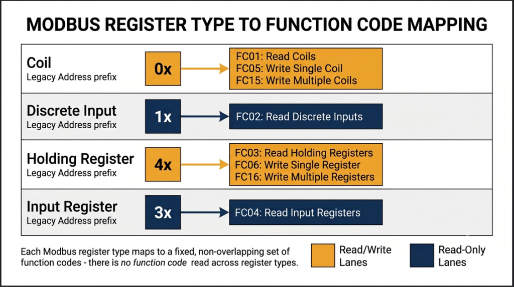
Figure 1. Each Modbus register type maps to a fixed, non-overlapping set of function codes – there is no function code that can read or write across register types.
The 0x/1x/3x/4x Addressing Convention (and Why It’s Inconsistent)
The 0x/1x/3x/4x prefix convention isn’t part of the official Modbus specification. It started with Modicon’s 984 PLC documentation in the 1970s, where each register type got a leading digit (0, 1, 3, or 4) and a four-digit offset. This became the industry standard because early documentation and devices copied it. However, the official Modbus protocol only defines function codes and 0-based addresses, not any required prefix.
This produces two separate sources of inconsistency that integrators run into constantly:
● Off-by-one translation: a holding register documented as “40001” corresponds to protocol address 0 on the wire, not address 40001 or even 1. The formula is protocol address = documented number − base offset (40001, 30001, etc.) − 1. Getting this wrong is the single most common cause of a read landing one register away from the intended value.
● Prefix omission and variation: many modern device manuals skip the legacy prefix entirely and just publish a raw 0-based or 1-based address (“register 800”, “address 0x0320”), or use a 6-digit variant (400801) instead of the classic 5-digit form (40801). Neither choice is wrong on its own, but when a manual doesn’t explicitly say which convention it’s using, the same number can point to a completely different physical register depending on the assumption you make.
Since the protocol doesn’t enforce any of these conventions, the safest approach is to treat each vendor’s register table as its own system. Always check if addresses are 0-based or 1-based, if a legacy prefix is used, and which function code the manual specifies. Don’t guess the function code based only on the leading digit.
Also check: How to Set Up a Modbus TCP Connection
Worked Example: Resolving a Vendor Register Documentation Ambiguity
Consider a common field scenario: a rooftop chiller’s Modbus register map lists “Supply Water Temperature -Register 800” with no further explanation of type or function code. Two chillers from two different manufacturers can both use this exact wording and mean entirely different things:
● Manufacturer A means holding register 40801, intended to be read with Function Code 03, because their firmware exposes all analog telemetry as holding registers for master compatibility.
● Manufacturer B means input register 30801, intended to be read with Function Code 04, because their firmware correctly separates read-only telemetry from writable configuration.
Here is the practical sequence to resolve the ambiguity in the field, without needing to call the manufacturer:
● Step 1 – Convert to a 0-based protocol address. Assuming a standard 1-based legacy convention with a 40001/30001 base, “register 800” as a holding register becomes protocol address 799 (800 − 1); as an input register, also 799 relative to its own 30001 base.
● Step 2 – Try Function Code 03 first at address 799. Because so many devices implement telemetry as holding registers regardless of “correct” typing, this succeeds more often than not. A valid response with a plausible raw value confirms Manufacturer A’s pattern.
● Step 3 – If Function Code 03 returns an Illegal Data Address exception (exception code 02), the value likely lives in the input register table instead. Retry the identical address with Function Code 04. A successful response confirms Manufacturer B’s pattern.
● Step 4 – Sanity-check the value against physical reality before trusting either result. A chiller supply water temperature reading in the raw hundreds (e.g., 452) strongly suggests a scaled value – divide by 10 to get 45.2°F – rather than a literal register or addressing error. Cross-referencing the returned value against an expected physical range is often faster than re-reading the manual a third time.
This process-confirming the 0-based address, trying the common function code, checking for exception responses, and validating the result against real-world values-solves most “register X” ambiguities during commissioning, so you usually won’t need to contact vendor support.
Reading 32-Bit and Float Values Across Two Registers
Every Modbus register, coil aside, is exactly 16 bits wide – there is no native 32-bit or floating-point register type. When a device needs to represent a 32-bit integer or an IEEE-754 single-precision float (common for energy meters, VFD speed feedback, and high-resolution flow totals), it splits the value across two consecutive 16-bit registers and documents them as a pair.
The complication is word order. Given a 32-bit value split into a high word (H) and low word (L), vendors are not consistent about which one comes first, or even about byte order within each word:
● Big-endian / “ABCD”: high word first, most significant byte first within each word – the most common convention and closest to how the value would be written on paper.
● Little-endian / “DCBA”: low word first, least significant byte first – matches native x86 memory layout, which is why some PC-originated devices default to it.
● Byte-swapped / “BADC” and “CDAB”: mixed conventions where the word order and byte order don’t match – rarer, but they exist, usually as an artifact of a driver library assumption baked into firmware years ago.
The quickest way to figure out which word order a device uses is to read a register pair with a known value, like a totalizer that matches a meter’s display, and try each word order until you get the right result. Most SCADA and driver software let you set the word order for each tag or device once you know it. Some common pitfalls include assuming that all devices use big-endian ordering (ABCD), or not noticing that different models from the same vendor may actually use different conventions. It’s also a common mistake to trust the word order listed in a generic Modbus guide without checking the device manual or testing with a real-world value. Mixing up word or byte order can produce values that look plausible but are completely wrong, so always verify against expected readings or specifications. Don’t assume one convention works for every 32-bit tag on a network with different vendors, because it often doesn’t.
FAQ: Modbus Register Questions Answered
What is the difference between a Modbus coil and a holding register?
A coil is a single read/write bit used to control a physical output like a relay or valve. A holding register is a 16-bit read/write word used for numeric values such as setpoints or configuration parameters. Coils use Function Codes 01/05/15; holding registers use 03/06/16.
What function code reads a Modbus holding register?
Function Code 03 (Read Holding Registers) reads one or more holding registers in a single request. Function Code 06 writes a single holding register, and Function Code 16 (0x10) writes multiple holding registers in one transaction.
How do you read a 32-bit value over Modbus?
Combine two consecutive 16-bit registers into one 32-bit value. Because vendors differ on word order (big-endian, little-endian, or byte-swapped), verify the correct order against a known reference value before trusting the result across an entire network.
What’s the difference between a discrete input and a coil?
Both are single-bit values, but a discrete input is read-only – representing a physical input like a limit switch – while a coil is read/write and represents a controllable output such as a relay or valve command.
Why do different vendors number Modbus registers differently?
The 0x/1x/3x/4x prefix convention is a legacy Modicon documentation practice, not a requirement of the official Modbus specification. Some vendors publish raw 0-based addresses instead, and off-by-one errors are common, so each device’s register map must be verified individually.
What happens if I use the wrong function code for a register type?
The slave device returns an exception response – typically Illegal Function or Illegal Data Address – because it has no matching entry in that data table at the requested address. It does not silently return incorrect data from the wrong table.
Confusing register types wastes more commissioning time than almost any other Modbus issue, because the protocol only gives you a generic error code. If you can spot the four register types by their bit width and access, treat the old 0x/1x/3x/4x prefixes as just a historical note, and follow the troubleshooting steps for vendor documentation issues, most Modbus register problems become quick to solve.
External References
- Modbus.org – official Modbus Application Protocol specification
- Schneider Electric – Modbus protocol implementation guide
- Control.com – Mitsubishi PLC to VFD Control: RS-485 Communication – Technical Articles
About The Author