
Every Arduino project, no matter how advanced it eventually becomes, starts with the same three building blocks: pinMode(), digitalRead(), and digitalWrite(). Get comfortable with these and blinking an LED stops being a magic incantation and starts being something you actually understand. This tutorial builds a simple button-and-LED circuit from scratch, explains exactly why “floating” inputs cause the flaky, random behavior that frustrates almost every beginner, and walks through the wiring and the code side by side so the underlying idea – a digital pin as a controllable voltage level – actually sticks.
What Digital I/O Means on an Arduino
“I/O” stands for input/output – the two directions information can flow through a pin. A digital pin on an Arduino Uno (built around the ATmega328P microcontroller) can only recognize two voltage states: roughly 5V, read as HIGH, or roughly 0V, read as LOW. There is no in-between; the chip’s internal circuitry rounds any voltage above about 3V up to HIGH and anything below about 1.5V down to LOW.
Digital pin – a physical connection point on the microcontroller that can be configured in software to either read (INPUT) or drive (OUTPUT) one of exactly two voltage levels, HIGH or LOW.
This is different from analog I/O, which measures or produces a continuous range of voltages (used by analogRead() and analogWrite(), covered in a separate tutorial on reading analog sensors). Digital I/O is simpler, faster, and is the right tool whenever the thing you’re controlling or sensing only has two meaningful states – on/off, pressed/released, open/closed.
Three functions do essentially all the work: pinMode() sets up a pin’s role once in setup(), digitalWrite() sends a voltage out of a pin configured as OUTPUT, and digitalRead() checks the voltage on a pin configured as INPUT or INPUT_PULLUP. Master these three and you can build buttons, switches, relays, buzzers, and simple LED indicators without touching anything more advanced.
pinMode() Explained: INPUT, OUTPUT, INPUT_PULLUP
pinMode() takes two arguments: the pin number, and the mode. It must run inside setup() before the pin is used, because it configures the physical hardware register that decides which direction voltage flows through that pin.
| void setup() { pinMode(13, OUTPUT); // pin 13 will drive an LED pinMode(2, INPUT_PULLUP); // pin 2 will read a button } |
The three available modes behave very differently, and mixing them up is one of the most common sources of beginner confusion:
| Mode | Internal Resistor | Default Pin State | Typical Use |
| INPUT | None | Floating (undefined) | Reading a sensor that actively drives HIGH/LOW |
| OUTPUT | None | LOW until written | Driving an LED, relay, transistor, or buzzer |
| INPUT_PULLUP | ~20–50 kΩ pulled to 5V | HIGH until pulled LOW | Reading a button/switch without an external resistor |
Pull-up resistor – a resistor connected between a pin and the positive supply voltage, holding that pin at a known HIGH level unless something actively pulls it LOW. The ATmega328P has one of these built into every digital pin, enabled simply by writing INPUT_PULLUP.
| NB There is no equivalent INPUT_PULLDOWN mode on classic AVR-based Arduino boards. If you need a pin to default LOW instead of HIGH, you must wire an external pull-down resistor (commonly 10kΩ) to GND yourself. |
digitalWrite() Explained With an LED Example
digitalWrite() sends a pin, already configured as OUTPUT, to either HIGH (approximately 5V) or LOW (0V). Nothing else – no brightness control, no in-between values. The classic first program almost everyone writes uses it to blink the Uno’s built-in LED on pin 13:
| void setup() { pinMode(13, OUTPUT); } void loop() { digitalWrite(13, HIGH); // LED on delay(500); // wait half a second digitalWrite(13, LOW); // LED off delay(500); } |
If you wire an external LED instead of using the built-in one, always place a current-limiting resistor (220Ω to 330Ω is typical) in series with it. An Arduino pin can only safely source about 20mA; without a resistor, an LED will draw far more than that and burn out almost immediately, sometimes damaging the pin along with it.
digitalRead() Explained With a Button Example
digitalRead() checks the current voltage on a pin configured as INPUT or INPUT_PULLUP and returns one of two constants: HIGH or LOW (internally these are just 1 and 0). It takes a single argument- the pin number – and is typically called inside loop() so the program keeps checking the pin continuously.
| void setup() { pinMode(2, INPUT_PULLUP); Serial.begin(9600); } void loop() { int buttonState = digitalRead(2); if (buttonState == LOW) { // LOW = pressed, when using INPUT_PULLUP Serial.println(“Button pressed”); } } |
| The logic is inverted With INPUT_PULLUP, the pin reads HIGH when the button is untouched and LOW the instant it’s pressed and connects the pin to GND. New Arduino users very often write “if (buttonState == HIGH)” out of habit and end up with a button that behaves backward. |
Why Floating Inputs Cause Random Behavior
Floating input – a digital pin set to INPUT with nothing driving it to a defined HIGH or LOW. It has no reference voltage, so it picks up tiny electrical noise from nearby wires, fluorescent lighting, USB cables, or even a finger held near the board, and reports HIGH and LOW unpredictably.
This is exactly what happens if you wire a button between a pin and GND, set that pin to plain INPUT, and skip the pull-up entirely. With nothing connected, the pin has no path to either 5V or 0V, so it drifts with whatever stray voltage is nearby. The diagram below compares the two situations directly.
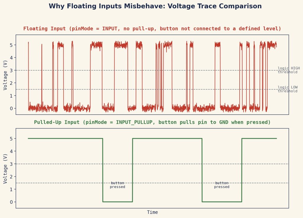
Figure 1. A floating input bounces erratically between HIGH and LOW, while a pulled-up input holds a clean, stable level until the button is actually pressed.
The fix is always the same: give the pin a defined resting state. INPUT_PULLUP does this in software with zero extra wiring, which is why it’s the recommended approach for virtually every simple button or switch circuit on Arduino.
Wiring a Button and LED Circuit Step by Step
This is the circuit used throughout this tutorial: a push button on pin 2 (using the internal pull-up) and an LED on pin 13 (through a current-limiting resistor). You’ll need:
- 1 Arduino Uno (or compatible board)
- 1 solderless breadboard
- 1 momentary push button
- 1 standard LED (any color)
- 1 resistor, 220Ω to 330Ω
- 4–5 jumper wires
- Place the push button and the LED on the breadboard, straddling the center gap so each leg lands in a separate row.
- Run a wire from the Arduino’s GND pin to the breadboard’s ground rail.
- Connect one leg of the button to the ground rail, and the other leg to Arduino pin 2.
- Connect the LED’s longer leg (anode) through the 220Ω resistor to Arduino pin 13.
- Connect the LED’s shorter leg (cathode) directly to the ground rail.
- Double-check the LED’s orientation and the resistor placement before powering the board – a reversed LED simply won’t light, but a missing resistor can damage it.
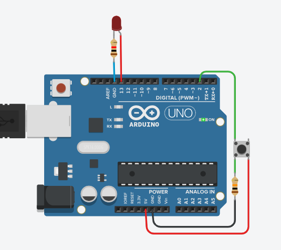
Figure 2. Complete button-and-LED wiring: pin 2 uses the internal pull-up so no external resistor is needed for the button, while pin 13 drives the LED through a 220Ω current-limiting resistor.
Full Code Walkthrough Line by Line
Putting both halves together, here is the complete sketch: the LED turns on for as long as the button is held down, and turns off when it’s released.
| // Button-controlled LED const int BUTTON_PIN = 2; const int LED_PIN = 13; void setup() { pinMode(BUTTON_PIN, INPUT_PULLUP); pinMode(LED_PIN, OUTPUT); } void loop() { int buttonState = digitalRead(BUTTON_PIN); if (buttonState == LOW) { digitalWrite(LED_PIN, HIGH); // button pressed -> LED on } else { digitalWrite(LED_PIN, LOW); // button released -> LED off } } |
Line-by-line breakdown
- const int BUTTON_PIN = 2; / const int LED_PIN = 13; – named constants instead of bare numbers, so the pin assignment only has to change in one place if you rewire later.
- pinMode(BUTTON_PIN, INPUT_PULLUP); – enables the internal pull-up resistor on pin 2, so it reads a stable HIGH by default.
- pinMode(LED_PIN, OUTPUT); – configures pin 13 to drive voltage out rather than read it.
- int buttonState = digitalRead(BUTTON_PIN); – reads the current voltage on pin 2 once per loop and stores it as HIGH (1) or LOW (0).
- if (buttonState == LOW) – checks for the pressed state, which is LOW because of INPUT_PULLUP’s inverted logic.
- digitalWrite(LED_PIN, HIGH); / digitalWrite(LED_PIN, LOW); – drives pin 13 to turn the LED on or off based on that reading.
Common Beginner Mistakes and How to Fix Them
- Forgetting pinMode() entirely. An unconfigured pin behaves unpredictably. Always set every pin’s mode in setup() before using it.
- Skipping the LED resistor. This isn’t a style choice – an LED with no current-limiting resistor draws too much current and typically fails within seconds. Use 220–330Ω for standard 5mm LEDs on 5V.
- Reading INPUT_PULLUP backward. Remember: pressed = LOW, released = HIGH. This trips up nearly every beginner at least once.
- Wiring an LED backward. LEDs are polarized – the longer leg (anode) goes toward positive, the shorter leg (cathode) toward ground. Reversed, it simply won’t light (this rarely damages it).
- Trying to dim an LED with digitalWrite(). It’s binary – on or off. Fading requires analogWrite() on a PWM-capable pin (marked with a ~ on most boards).
- Ignoring switch bounce. A mechanical button’s contacts can rapidly flicker on first contact, which can register as several presses instead of one in fast-reacting code. This is normally handled with simple software debouncing, covered in a dedicated future tutorial.
FAQ: Arduino Digital I/O Questions Answered
What does pinMode() do in Arduino?
pinMode() configures how a digital pin behaves before you use it. It tells the microcontroller whether the pin should act as an OUTPUT (driving a voltage out, such as to an LED), a plain INPUT (reading a voltage that something else controls), or an INPUT_PULLUP (reading a voltage while using the chip’s own internal pull-up resistor). Skipping pinMode() leaves a pin in an unreliable default state.
Why do I need INPUT_PULLUP on Arduino?
A digital input with nothing connected has no defined voltage, so it “floats” and reads randomly due to electrical noise. INPUT_PULLUP solves this by connecting a resistor inside the microcontroller between the pin and 5V, holding the pin at a steady HIGH until a button or switch pulls it LOW. It removes the need for an external resistor on simple button circuits.
What is the difference between digitalRead() and digitalWrite()?
digitalWrite() sends a voltage out of a pin that is set to OUTPUT, turning something like an LED on or off. digitalRead() does the opposite: it checks the current voltage on a pin set to INPUT or INPUT_PULLUP and returns HIGH or LOW. One pin controls the outside world; the other listens to it.
Why does my Arduino LED not light up even though the code looks correct?
The most common causes are a reversed LED (LEDs only conduct in one direction), a missing current-limiting resistor causing the LED to fail, a loose breadboard connection, or forgetting pinMode(pin, OUTPUT) in setup(). Checking LED polarity and confirming the pin number in code matches the physical wire resolves most cases.
Can I use digitalWrite() to dim an LED?
No. digitalWrite() only supports two states, HIGH (full on) and LOW (full off), so it cannot produce partial brightness. Dimming requires analogWrite(), which uses PWM (pulse-width modulation) on supported pins to simulate intermediate voltage levels by rapidly switching the pin on and off.
References
About The Author