Once you understand ladder logic basics and timers, the next step is learning counters. Whenever a process needs to track how many times something happens, like bottles filled, parts made, or pallets stacked, a counter instruction handles the counting in the background.
This guide explains the three main counter instructions you’ll use: CTU (count up), CTD (count down), and CTUD (up/down). Each section has a real ladder logic example, explains how the preset and accumulated values work, and points out common mistakes beginners make with reset wiring. By the end, you’ll know how to pick the right counter, build a reliable reset circuit, and read counter syntax for Allen-Bradley, Siemens, and Mitsubishi PLCs.
What a PLC Counter Instruction Actually Does
A counter instruction keeps track of how many times a trigger changes from off to on, known as a rising edge, and compares this total to a target value called the preset. All counter instructions, no matter the brand, use the same three main data points:
- Accumulated value (ACC / CV) – the running count, stored as an integer.
- Preset value (PV) – the target the accumulated value is compared against.
- Done bit (DN / Q) – turns on once the accumulated value reaches the preset, and stays on until the counter is reset.
A key point many beginners miss is that a counter only increases on a rising edge of its count input, not while the input stays on. If a sensor stays closed for two seconds, the counter only adds one, right when it changes from off to on, not for the whole time it stays closed. This is what makes counters different from timers, which keep counting as long as their input is true.
KEY CONCEPT
A counter tracks changes, not how long something lasts. A timer measures time, not the number of changes. Mixing these up is the most common reason a beginner’s counter program doesn’t work as expected.
CTU (Count Up) Explained With a Ladder Example
CTU is the counter you’ll use most. Each time its count input (CU) goes from off to on, the accumulated value goes up by one. When this value reaches the preset, the done bit (DN) /Q turns on and stays on. It won’t reset by itself, even if the count input keeps pulsing above the preset.
The example below counts parts on a conveyor. Sensor_1 pulses once per part; C5 counts up toward a preset of 50. A separate reset rung, driven by Reset_PB, clears the counter back to zero and turns C5.DN back off.
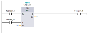
Figure 1. CTU counter rung: Sensor_1 increments C5 on each rising edge; a separate reset rung (bottom) clears the count via the R input.
Here’s how the rung works: when Sensor_1 closes, the CU input on counter C5 gets a rising edge, and its accumulated value (CV) goes up by one. When CV reaches the preset of 50, the DN output turns on. You can use this bit elsewhere in your program to trigger actions like moving a pallet or closing a case. The count keeps going past 50 if Sensor_1 keeps pulsing; DN stays on until the counter is reset.
CTD (Count Down) Explained With a Ladder Example
CTD works the opposite way: it starts from a set value and counts down to zero each time its count-down input (CD) gets a rising edge. The done bit turns on when the value reaches zero. On some platforms, it turns on when it reaches a preset of zero instead, so always check your vendor’s documentation, as this is one area where behavior can differ.
CTD is the natural fit for inventory-style counting – tracking how many items remain in a batch rather than how many have been produced. In the example below, Batch_Start loads the counter with a starting value of 20 via the LD (load) input, and Part_Out decrements it by one each time a part leaves the batch station.
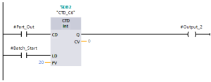
Figure 2. CTD counter rung: Part_Out decrements C6 on each rising edge; Batch_Start loads the initial batch quantity via the LD input.
This pattern is a bit different from CTU. Instead of counting up to a target, the program watches for when the value hits zero; that’s when C6.DN turns on, and the batch is done. Loading the counter (LD) is not the same as resetting it. Loading sets the value to what’s in the load register, while resetting clears it to zero. With CTD, you usually want to load, not reset, at the start of each new batch.
CTUD (Up/Down) Counters for Bidirectional Counting
CTUD lets you count up and down in one instruction, with separate inputs for count-up (CU), count-down (CD), reset (R), and load (LD). Use CTUD when a process can go both ways. A good example is a gate with two sensors: one adds to the count when something enters, and the other subtracts when something leaves.
The example below tracks how many pallets are currently in a staging bay. In_Sensor increments the count as pallets enter; Out_Sensor decrements it as they leave. A separate Shift_Reset rung clears the count to zero at the start of each shift, when the bay is physically verified empty.
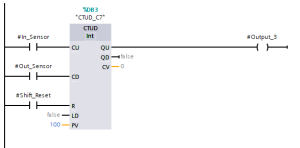
Figure 3. CTUD counter rung: In_Sensor and Out_Sensor drive the up and down inputs independently; Shift_Reset clears the accumulated value at shift change.
Most platforms show two done bits for CTUD: QU (or DN), which turns on when the count reaches the preset from below, and QD (or UN, meaning “underflow”), which turns on if the count goes below zero. The underflow bit is important. If you don’t check it, a wiring problem or missed sensor pulse can make your count go negative, showing an impossible number of pallets. A good CTUD program checks for underflow and raises an alarm instead of trusting the count without question.
Counters vs Timers: When to Use Each
Timers and counters are both basic instructions, and beginners often mix them up because both can seem to solve similar problems. The key difference is what you’re measuring: timers track time, while counters track the number of events.
| Question | Use a Timer | Use a Counter |
| What am I measuring? | Duration — how long a condition has been true | Occurrences — how many times an event happened |
| Does the input need to stay on? | Yes, continuously, for the timer to keep accumulating | No — only a momentary rising edge is needed per count |
| Typical application | Delay a motor start by 5 seconds; run a pump for 30 seconds | Count parts, cycles, pallets, or batches |
| Resets automatically? | Some types (TON) reset when input goes false; others (RTO) require explicit reset | Never resets automatically — always requires an explicit reset or load rung |
| Common instruction names | TON, TOF, RTO | CTU, CTD, CTUD |
Table 1. Deciding between a timer and a counter instruction.
Building a Safe Counter Reset Circuit
A counter that never resets isn’t helpful for repeating processes, but a poorly designed reset circuit can cause two common problems: double-counting (when the reset stays true for more than one scan and the count input is also active, so the counter triggers again right after clearing) and missed resets (when the reset depends on a bit that never actually turns on during real operation).
Follow these three rules for a reset rung that behaves predictably:
- Connect the reset (R) input to a single, clean momentary contact, like a push button, a one-shot internal bit, or a done bit from another instruction. Never use the same sensor for both counting and resetting.
- If the reset condition comes from logic (for example, “reset when a case-full sensor sees the case AND the counter is done”), use a one-shot (rising-edge detection) instruction. This way, the reset only pulses for one scan, not for as long as the condition is true.
- Test the reset rung by itself before adding it to the full program. First, make the count reach the preset, then trigger just the reset condition. Check that the accumulated value goes back to zero and the done bit turns off on the next scan.
FIELD NOTE
On the bottle-counting conveyor example later in this article, the reset condition is a case sensor — not the same photo-eye used to count bottles. Sharing a single sensor between the count and reset functions is one of the most common root causes of unreliable counting on real production lines.
Common Counter Mistakes (Double-Counting, Missed Resets)
- If you wire the count input to a sensor that bounces, like a mechanical limit switch, it can register several rising edges for one event. Fix this by using a snap-action switch or adding a short one-shot delay in software before the signal reaches the counter.
- Remember, CTU counters don’t stop counting when they reach the preset. The done bit turns on, but the accumulated value keeps going up if the count input keeps pulsing. If your logic expects the counter to stop at the preset, you might get an overflow when the value goes past the data type’s limit.
- Don’t mix up reset and load on a CTD or CTUD counter. Reset clears the value to zero, while load sets it to the value on the load input. Using the wrong one is a common reason for batch count errors right from the start.
- If you use the same sensor for both counting and resetting, the counter resets on the same edge that should have increased the count. This means it never counts past one.
- Don’t forget about power-cycle behavior. Depending on your platform and whether the counter’s value is retentive or not, a power cycle might erase the count. Always check this for counters that need to keep their value after a restart, like a shift total.
Worked Example: Bottle-Counting Conveyor
This example puts together a CTU counter, a separate reset condition, and a downstream action, diverting a full case off the main line into a complete, practical two-rung program.
- Rung 1: Photo_Eye counts each bottle passing a fixed point. Counter C10 is preset to 24, matching the number of bottles per case.
- Rung 2: When C10.DN turns on (after 24 bottles are counted), the Divert_Sol output activates. This triggers a pneumatic diverter that moves the full case off the main conveyor to a case-sealing station.
- Rung 3: A separate Case_Sensor, mounted at the diverter (not the bottle-counting photo-eye), resets C10 after the case has been diverted. This way, the next case starts counting from zero only after the previous one has left.
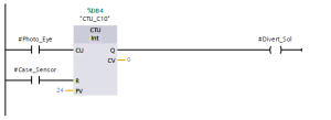
Figure 4. Complete bottle-counting example: The CTU counts bottles per case, a done-bit contact triggers the diverter solenoid, and a separate case sensor resets the counter.
This setup- count, act when done, and reset from a separate downstream confirmation- is a pattern you’ll use often in real automation programs. You might change the sensors or preset values, but the three-rung structure stays the same.
Vendor Syntax Differences (Allen-Bradley, Siemens, Mitsubishi)
The main idea is the same on all platforms, but instruction names, input/output labels, and default settings can be different and cause confusion when switching vendors. This table shows how the terms used in this article match up with those on the three most common platforms.
| Concept | Allen-Bradley (Studio 5000 / RSLogix) | Siemens (TIA Portal) | Mitsubishi (GX Works) |
| Count-up instruction | CTU | S_CU / CTU (IEC counter) | C (with OUT C␣K␣ format) |
| Count-down instruction | CTD | S_CD / CTD | Achieved via separate down-counting logic or IEC counter FB |
| Up/down instruction | CTUD (via paired CTU/CTD on same address) | CTUD (IEC counter) | Achieved via combined ladder logic; no native CTUD in classic FX instruction set |
| Accumulated value | ACC | CV | Current value (C␣ register) |
| Preset value | PRE | PV | K constant or D register |
| Done bit | .DN | Q | Counter contact (C␣) |
| Reset | RES instruction on same counter address | R input on the counter FB | RST C␣ instruction |
Table 2. Counter instruction terminology by platform.
Here are two practical tips if you’re switching between platforms. First, classic Mitsubishi FX-series PLCs don’t have a built-in CTUD block like Allen-Bradley and Siemens. You usually build bidirectional counting with ladder logic, or use an IEC-compliant function block on newer models like the FX5U. Second, Allen-Bradley’s CTU and CTD share the same counter address when used together, while Siemens and most IEC 61131-3 systems use CTUD as a single, separate instruction. Always check your platform’s instruction reference before assuming the syntax is the same.
FAQ: PLC Counter Questions Answered
What is the difference between CTU and CTD in PLC?
CTU (count up) increases its accumulated value by one on each rising edge of its count input and turns on its done bit once that value reaches the preset. CTD (count down) does the opposite — it starts from a loaded value and decreases toward zero, turning on its done bit once the accumulated value reaches zero.
How do you reset a counter in ladder logic?
Drive the counter’s reset (R) input, or a dedicated reset instruction such as Allen-Bradley’s RES, from a single momentary contact that is separate from whatever drives the count input. This clears the accumulated value to zero and turns off the done bit. Avoid sharing the same sensor for both counting and resetting.
What is a CTUD instruction used for?
CTUD (up/down counter) is used whenever a quantity can both increase and decrease; most commonly counting items entering and leaving a physical space, such as parts in a staging buffer or vehicles in a parking area, using two separate sensors driving the up and down inputs independently.
Does a PLC counter reset automatically when power is lost?
It depends on whether the counter’s accumulated value is stored in retentive or non-retentive memory, which varies by platform and by how the tag is configured. If a count must survive a power cycle, such as a shift total, this needs to be explicitly configured and tested, not assumed.
Why does my PLC counter count more than once per event?
This is almost always caused by contact bounce on a mechanical sensor, or by a count input that stays true for multiple scans while being interpreted as multiple rising edges due to a logic error elsewhere in the program. Debounce the input in hardware or with a one-shot instruction before it reaches the counter.
Where to Go Next
Counters and timers together handle most of the basic sequencing you’ll need for real automation projects. Next, you should learn about PLC data types, since counter preset and accumulated values are just integer tags. Then, try building a full sorting-conveyor project that uses counters, sensors, and actuator outputs in one working program.
- Related: How to Program a PLC in Ladder Logic
- Related: PLC Timer Programming Tutorial: Mastering On-Delay Timers (TON)
- Related: Mitsubishi GX Developer Timer Tutorial
- Up next: PLC Data Types Explained: BOOL, INT, REAL, and Structures.