How to Program a PLC in Ladder Logic
Ladder Logic remains the most widely used programming language for industrial automation. In this guide, we’ll walk you through the basics of PLC programming, from setting up inputs and outputs to writing structured logic for real-world applications. Whether you’re a beginner or looking to refine your skills, this tutorial will help you master essential Ladder Logic concepts.
Ladder Logic remains the most widely used programming language for industrial automation. Its graphical representation, resembling electrical relay control circuits, makes it intuitive for engineers and technicians. In this guide, we will walk through the basics of PLC programming in Ladder Logic, from setting up inputs and outputs to writing structured logic for controlling industrial processes.
Understanding Ladder Logic
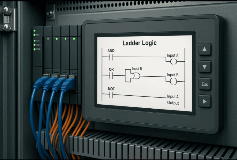
Ladder Logic consists of rungs (horizontal lines) that execute sequentially from top to bottom. Each rung represents a control statement that determines how outputs respond to inputs. Understanding the core elements of Ladder Logic is essential for creating effective automation programs.
Key Components of Ladder Logic
- Inputs (Contacts): Represented by symbols such as normally open (NO) and normally closed (NC) contacts. These correspond to physical input devices such as push buttons, sensors, or switches.
- Outputs (Coils): Represent actuators like motors, lights, or solenoids. Outputs are energized when conditions on the rung are met.
- Logic Functions: Includes AND, OR, latching, timers, counters, and comparisons to create complex automation sequences.
Step-by-Step Guide to Programming a PLC in Ladder Logic
Step 1: Define the Process
Before writing a program, identify:
- The inputs (e.g., sensors, buttons)
- The outputs (e.g., motors, alarms)
- The logic needed to achieve the desired automation
Step 2: Configure PLC Hardware
- Select a PLC model suitable for your application.
- Assign input and output addresses based on the wiring layout.
- Establish communication with the PLC software.
Step 3: Write the Ladder Logic Program
Using PLC programming software:
- Insert rungs and define input conditions.
- Add output coils to control actuators.
- Implement logic elements like timers and counters.
Example: Basic Start-Stop Motor Control
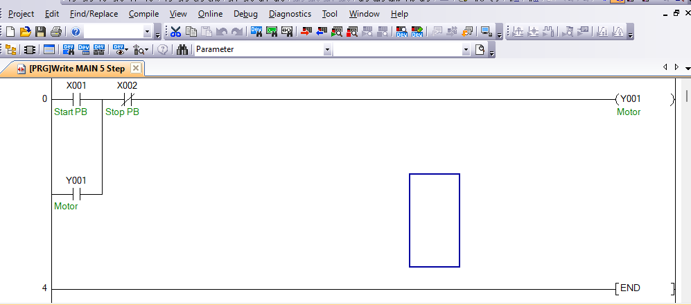
- Start PB (Push Button): Normally open contact to start the motor.
- Stop PB: Normally closed contact to stop the motor.
- Motor Coil: Energized when Start PB is pressed and remains ON until Stop PB is pressed.
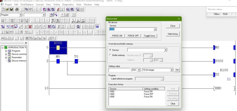
Step 4: Test and Debug
- Simulate the program to check for errors.
- Download the program to the PLC.
- Run tests with actual hardware and make adjustments if needed.
Step 5: Monitor and Optimize
- Use PLC monitoring tools to track real-time execution.
- Optimize logic for efficiency and troubleshooting.
Ladder Logic In PLCs
Ladder Logic provides an intuitive way to program PLCs for industrial automation. Mastering the basics of contacts, coils, and logic functions allows you to create efficient control systems. As you advance, explore additional functions like analog inputs, PID control, and network communication for more complex automation tasks.
