Boolean Algebra & Logic Gates in PLCs
This comprehensive guide will walk you through the critical concepts of Boolean algebra in PLCs, from basic laws to practical implementations.
In Programmable Logic Controllers (PLCs), understanding the fundamental principles of Boolean algebra isn’t just academic, it’s essential for designing efficient, reliable automation systems. Whether you’re optimizing manufacturing processes, developing safety protocols, or troubleshooting control systems, Boolean algebra provides the mathematical framework that makes it all possible.

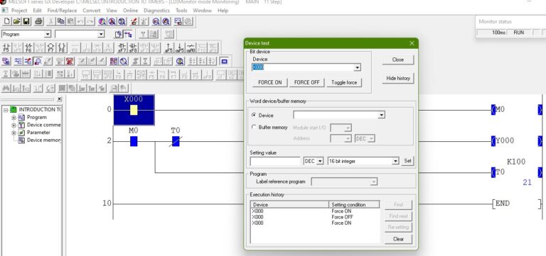
Figure 1: A modern PLC control panel showing ladder logic implementation of Boolean operations for industrial automation. Image used courtesy of Bob Odhiambo.
What Is Boolean Algebra in PLC Programming?
Boolean algebra, developed by mathematician George Boole in the mid-19th century, forms the foundation of digital logic. In the context of industrial automation and PLCs, Boolean algebra deals with binary values:
- 1 (TRUE/ON): Represents an activated condition or energized state
- 0 (FALSE/OFF): Represents a deactivated condition or de-energized state
These binary states perfectly match the on/off nature of control systems, making Boolean algebra the ideal mathematical system for designing PLC logic. Every decision in your automation system, whether a motor should run, a valve should open, or an alarm should activate, can be expressed through Boolean operations.
Related Reading: How to Program a PLC using Ladder Logic
The Essential Boolean Laws for PLC Programmers
Understanding these fundamental Boolean laws will transform your approach to designing and optimizing PLC programs. Let’s explore each law with practical industrial examples.
1. Identity Laws: The “No Change” Rule
The Identity Laws establish that when a variable is combined with certain constants, the variable remains unchanged:
| Law | Expression | Meaning |
| OR Identity | A + 0 = A | Adding 0 to anything keeps it the same |
| AND Identity | A · 1 = A | Multiplying by 1 keeps it the same |
Real-World Application: Imagine a production line where a machine starts when either:
- The START button is pressed
- An override signal is active (which defaults to 0)
Since A + 0 = A, the machine will start based solely on whether the START button is pressed, as adding the inactive override signal (0) doesn’t change the result.
2. Null (Dominance) Laws: The “All or Nothing” Rule
These laws define what happens when combining variables with extreme values:
| Law | Expression | Meaning |
| OR Dominance | A + 1 = 1 | Adding 1 to anything makes it 1 |
| AND Dominance | A · 0 = 0 | Multiplying anything by 0 makes it 0 |
Real-World Application: Emergency stop (E-STOP) implementation relies heavily on the AND Dominance law. When an E-STOP is pressed, it should immediately halt operations regardless of other conditions. By incorporating the E-STOP as an AND condition (where E-STOP = 0 when pressed), the system ensures that A · 0 = 0, guaranteeing the machine stops. Learn more in Safety Systems in PLC Design.
3. Idempotent Laws: The “Double Effect” Rule
The Idempotent Laws state that repeating the same condition doesn’t change the outcome:
| Law | Expression | Meaning |
| OR Idempotent | A + A = A | Adding something to itself does nothing |
| AND Idempotent | A · A = A | Multiplying something by itself does nothing |
Real-World Application: In safety-critical systems, engineers might mistakenly duplicate safety interlocks, thinking it adds redundancy. Understanding that A · A = A shows that repeating identical conditions adds complexity without increasing reliability.
4. Complement Laws: The “Opposites Rule”
These laws describe what happens when a condition is combined with its opposite:
| Law | Expression | Meaning |
| OR Complement | A + Ā = 1 | A condition and its NOT version always give 1 |
| AND Complement | A · Ā = 0 | A condition and its NOT version always give 0 |
Real-World Application: In a lighting control system, lights must be ON in either daytime mode or night mode. Since one must be true at any given time (they’re complements of each other), the OR Complement law ensures the lights are always powered.
5. Commutative Laws: The “Order Doesn’t Matter” Rule
The Commutative Laws establish that input order doesn’t affect results:
| Law | Expression | Meaning |
| OR Commutative | A + B = B + A | Order in OR logic doesn’t matter |
| AND Commutative | A · B = B · A | Order in AND logic doesn’t matter |
Real-World Application: A conveyor belt can be stopped by either a manual stop button or an automatic jam sensor. The Commutative Law confirms that either condition will stop the conveyor regardless of how they’re arranged in the program. The order doesn’t change the logic. Dive deeper in Optimizing PLC Ladder Logic Design.
6. Associative Laws: The “Grouping Doesn’t Matter” Rule
These laws state that different groupings of inputs produce the same result:
| Law | Expression | Meaning |
| OR Associative | (A + B) + C = A + (B + C) | OR grouping doesn’t matter |
| AND Associative | (A · B) · C = A · (B · C) | AND grouping doesn’t matter |
Real-World Application: When implementing a machine startup sequence requiring three safety conditions (door closed, pressure normal, temperature acceptable), the Associative Law proves that any grouping of these conditions will produce the same result.
7. Distributive Law: The “Multiplication Over Addition” Rule
This powerful law helps simplify complex expressions:
| Law | Expression |
| Distributive | A · (B + C) = (A · B) + (A · C) |
Real-World Application: Consider a motor control system where the motor should start if:
- The start button is pressed (A)
- Either the foot pedal (B) or proximity sensor (C) is activated
This can be expressed as A · (B + C), which equals (A · B) + (A · C). The Distributive Law allows us to implement this logic in different but equivalent ways.
8. Absorption Law: The “Redundancy Rule”
This law removes unnecessary conditions:
| Law | Expression | Meaning |
| OR Absorption | A + (A · B) = A | Extra condition is unnecessary |
| AND Absorption | A · (A + B) = A | Extra condition is unnecessary |
Real-World Application: In a simple conveyor control, if the main power switch must be ON for operation, additional checks of the power state are redundant. Understanding the Absorption Law helps eliminate these unnecessary conditions.
Practical Benefits of Understanding Boolean Algebra for PLC Programming
Understanding Boolean algebra delivers several concrete benefits for automation professionals:
- Streamlined Logic: Eliminate unnecessary rungs and contacts in ladder logic
- Faster Execution: Simplified programs execute more quickly and efficiently
- Enhanced Troubleshooting: Cleaner logic is easier to debug and maintain
- Optimized Memory Usage: Compact programs use fewer PLC resources
- Improved Reliability: Logical consistency reduces the chance of errors
Implementing Boolean Algebra in Real PLC Projects
Boolean algebra may seem abstract initially, but its practical applications are immediate and significant. Here’s a step-by-step approach to applying these principles in your next automation project:
- Document Requirements: Clearly define all inputs, outputs, and logical conditions
- Create Truth Tables: Map all possible input combinations and desired outputs
- Express in Boolean Terms: Write the initial Boolean expressions
- Apply Simplification Laws: Use the laws above to reduce complexity
- Implement in Ladder Logic: Convert your simplified expressions to PLC code
- Test and Validate: Verify that the simplified logic works correctly
Boolean Algebra as Your Competitive Edge
Mastering Boolean algebra gives automation engineers a powerful toolset for creating elegant, efficient control systems. By understanding and applying these fundamental laws, you’ll develop PLC programs that are not only more compact and efficient but also easier to maintain and troubleshoot.
Whether you’re designing new automation systems or optimizing existing ones, these Boolean principles will help you create solutions that stand the test of time. Take the time to master these concepts, and you’ll distinguish yourself as a truly proficient PLC programmer.
Further Resources
Looking to deepen your understanding of Boolean algebra and PLC programming? Check out these valuable resources:
- Truth Tables and K-Maps for Logic Simplification
Have you applied Boolean algebra principles in your PLC projects? Share your experiences in the comments below!