
Modbus TCP is still the main way to connect a PLC to a SCADA system when both use Ethernet. It’s simple, free, and most automation vendors support it. Most problems come from a few common causes: using the wrong port, mismatched unit IDs, firewalls blocking traffic, or register maps that don’t match SCADA tags.
This guide walks you through each step: setting up the PLC as a Modbus TCP server, connecting your SCADA client to the PLC on port 502, and testing the connection by reading a real register before adding all your tags. At the end, you’ll find a troubleshooting table for common issues like connection refused, timeouts, or odd data, plus a function code reference and security tips.
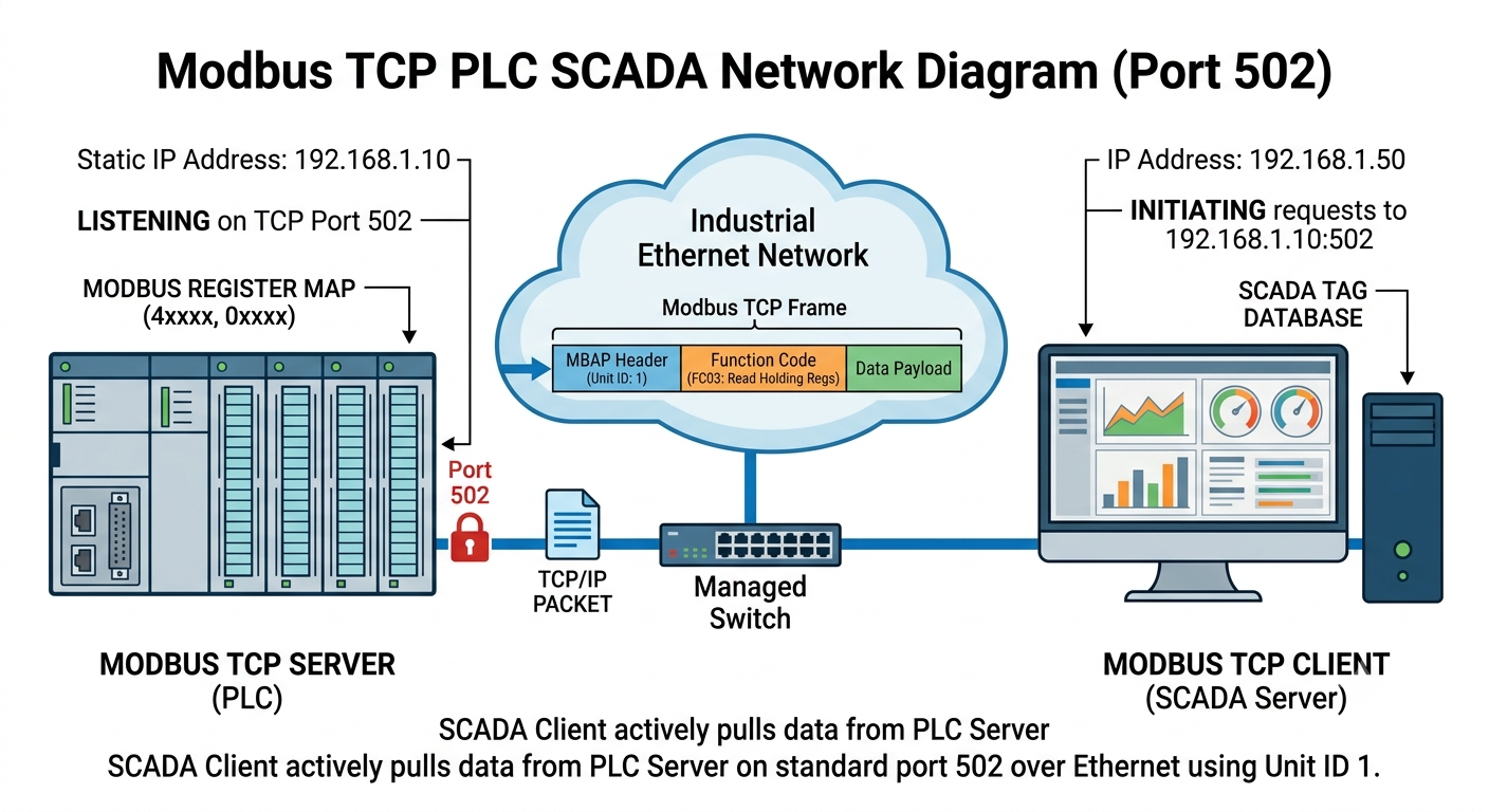 Figure 1. Visual network layout illustrating a SCADA system acting as the Modbus TCP client initiating communication with a PLC configured as the Modbus TCP server. Image used courtesy of the author.
Key Terms Used in This Guide
Modbus TCP server: This is the device that holds the data and answers requests. In this setup, it’s the PLC. Older Modbus documentation calls this the “slave.”
Modbus TCP client: This device starts requests and reads or writes data. In this setup, it’s the SCADA system. Older documentation calls this the “master.”
Unit ID: This is a one-byte identifier (0–255) included in every Modbus TCP frame. On a native Ethernet PLC, it’s often set to a fixed value like 1 or 255. On a Modbus TCP-to-RTU gateway, it picks which serial device should respond.
Function code: This is a number in the Modbus request that tells the server what action to take, like reading holding registers or writing a single coil. More details are covered later in this guide.
Modbus TCP vs Modbus RTU: A 60-Second Refresher
Modbus RTU and Modbus TCP use the same data model, register types, function codes, and request/response structure. The main difference is the physical layer they use, which often confuses beginners.
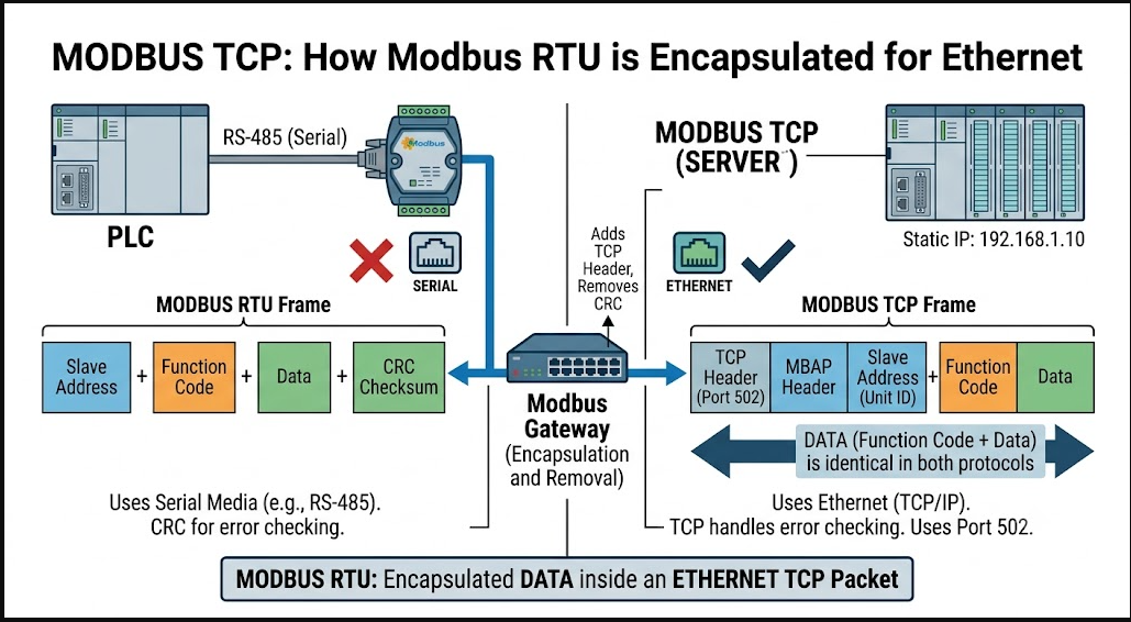 Figure 2. A visual breakdown of serial encapsulation, showing how data payload structures map across RS-485 and Industrial Ethernet networks using a Modbus gateway. Image used courtesy of the author.
Modbus RTU runs over serial links, typically RS-485, using binary framing and a CRC checksum to detect transmission errors. Devices are identified on the wire by a slave address (1–247), and only one device can talk at a time because RS-485 is a shared, half-duplex bus. Modbus RTU is inexpensive, deterministic, and tolerant of long cable runs, which is why it’s still everywhere on the plant floor for VFDs, meters, and simple I/O modules.
Modbus TCP sends the same request and response data inside a standard TCP/IP packet over Ethernet, not over a serial bus. It doesn’t include a CRC in the Modbus TCP frame because TCP/IP already checks for errors. Instead of a slave address, Modbus TCP uses a Unit ID in the MBAP header. For PLCs with Ethernet, the Unit ID is usually just a formality. On a Modbus TCP-to-RTU gateway, the Unit ID tells the gateway which serial device should respond.
In practice, use Modbus TCP if both the PLC and SCADA platform have Ethernet ports and are on the same network or can communicate across networks. Use Modbus RTU for older field devices that only support RS-485, or when long cable runs make serial connections easier than installing new Ethernet. Many projects use both: RTU for field devices through a gateway, and TCP for the SCADA side. This setup is explained in the RS-485 field guide mentioned at the end of this article.
What You Need Before You Start (IP Plan, Port 502, Unit IDs)
Most Modbus TCP setups fail due to missing preparation, not because of hidden settings. Make sure you check each of the following before starting the PLC configuration.
1. A firm IP address for the PLC
The PLC should have a static IP address or a DHCP reservation tied to its MAC address. It should be on the same subnet as the SCADA server or reachable through the correct router and firewall settings. Don’t use plain DHCP without a reservation. If the IP lease changes, the SCADA client will lose its connection for no obvious reason, and you might waste time troubleshooting a ‘communication fault’ that is just a changed IP address.
2. Port 502 available end to end
Modbus TCP uses TCP port 502 by default, which is registered with IANA for this purpose. If the PLC and SCADA server are on different VLANs or subnets, make sure port 502 is allowed through every firewall and Layer 3 switch ACL in between. It’s not enough for the device to respond to ping; it must be allowed on that specific port. A device that responds to ping but refuses the Modbus session is a common early symptom, and it almost always comes down to a firewall rule.
3. A defined Unit ID
Choose the Unit ID that the PLC will use, and make sure the SCADA side uses the same value. For PLCs with native Ethernet and no serial devices, common defaults are 1, 0, or 255. Check your vendor’s documentation, as some PLCs ignore the Unit ID on native TCP connections, while others require it to match exactly.
4. A register map
Before you configure anything, write down which PLC memory areas map to which Modbus register addresses, and what data type each one uses (like 16-bit integer, 32-bit float across two registers, or a boolean packed into a coil). A simple table like the one below, kept next to the PLC program and the SCADA tag database, will save you much more time than it takes to make.
| Register Address | PLC Tag | Data Type | Description |
| 40001 (HR 0) | Tank1_Level | 16-bit INT, scaled 0–1000 | Tank 1 level, 0–100.0% |
| 40002–40003 (HR 1–2) | Line_Speed | 32-bit FLOAT | Conveyor line speed, m/min |
| 00001 (Coil 0) | Pump1_Run | Boolean | Pump 1 run status |
| 00002 (Coil 1) | Pump1_Start_Cmd | Boolean, writable | SCADA-issued start command |
Table 1. Sample Modbus Register Map.
The 40001-style addressing above follows the classic Modicon convention, where holding registers start at 40001 and coils at 00001. Many modern tools use zero-based addressing at the protocol level, like register 0 instead of 40001. Check which convention your PLC firmware and SCADA driver use. A mismatch here, even by one or by 40000, is a common cause of incorrect values that seem to work but are actually wrong.
5. Network hardware and cabling in place
Check that the PLC’s Ethernet port, the switch it connects to, and the SCADA server’s network interface all use hardware that can handle the traffic. Unmanaged switches are fine for small setups, but managed switches with VLANs are better for larger systems. If the PLC and SCADA server are on different subnets, make sure routing is set up before troubleshooting Modbus. A Layer 3 issue can look just like a Modbus problem until you check the network.
Step 1: Configuring the PLC as a Modbus TCP Server
Menu names may differ by vendor, but the basic steps are the same on almost every PLC that supports Modbus TCP natively or with an add-on.
- Assign the static IP address, subnet mask, and (if needed) gateway to the PLC’s Ethernet port using the vendor’s configuration software or the PLC’s own web interface.
- Enable the Modbus TCP server function. On PLCs where Modbus TCP is built in (like Schneider Modicon, many Click and AutomationDirect PLCs, and most “generic Ethernet” controllers), this is usually a checkbox or a communication object you add to the project. On PLCs that use a different native protocol (such as Allen-Bradley’s EtherNet/IP or Siemens’ S7 communication), Modbus TCP usually needs an add-on instruction, a communication module, or a separate software option. Check this before assuming it’s available out of the box.
- Set the listening port. Keep it at the default 502 unless you have a specific reason to change it, like running several virtual Modbus servers on one IP or following a security policy that requires a different port.
- Set or confirm the Unit ID the server will respond to, matching what you decided on in the prerequisites step.
- Map internal PLC memory or tags to Modbus register addresses. Some PLCs do this automatically by exposing their entire tag database over Modbus with an implicit addressing scheme. Others require you to set up a mapping table where you assign each tag a coil, input, or register address.
- Save the configuration and download it to the PLC. Confirm the PLC comes back online and that the Ethernet port shows a link light and, if the vendor tool supports it, an active TCP listener on port 502.
Vendor Note
Modbus TCP implementations can vary between vendors, so always check your PLC’s user manual for the exact menu path and any licensing requirements. Don’t assume a feature will work the same way as it did on your last project. Tutorials and real PLC configuration screens often differ at this point.
Step 2: Pointing Your SCADA Client at the PLC
Once the PLC is set up as a Modbus TCP server, you need to configure the SCADA platform as the client that polls it. Most SCADA and HMI platforms use a similar process for adding a new Modbus TCP device.
7. In the SCADA project, add a new device or channel and select the Modbus TCP/IP driver (sometimes listed as “Modbus Ethernet” or “Modicon Modbus TCP” depending on the platform).
8. Enter the PLC’s static IP address and the port number — port 502, unless you deliberately changed it in Step 1.
9. Enter the Unit ID exactly as it is set in the PLC configuration. If the Unit IDs don’t match, the connection may open at the TCP level but won’t return valid data. This is a common cause of problems.
10. Set a scan rate (poll interval) that fits your data. For fast-changing values like line speed, use 250 to 500 ms. For slow-changing status bits, 1 to 5 seconds is enough. Polling too quickly can cause timeouts that look like connection issues but are actually due to bandwidth or PLC load limits.
11. Add tags to the SCADA tag database that point to the register addresses from your register map, and make sure to use the correct data type for each one. For example, mapping a 32-bit float as a 16-bit integer will give you a meaningless value, even if the connection is working.
12. Save and activate the device driver, then check the SCADA platform’s diagnostics or device status page for a “connected” or “good” status before moving on to the test in Step 3.
Step 3: Testing the Connection With a Register Read
Before you connect everything to your full HMI screens, test the setup by reading one known register and checking that the value matches what you expect.
A free standalone Modbus client tool, like Modbus Poll or QModMaster, is the fastest way to see if a problem is in the PLC, the network, or the SCADA configuration. This method tests the connection without using the SCADA platform.
13. Install a Modbus TCP test client on a laptop connected to the same network as the PLC.
14. Create a new connection using the PLC’s IP address, port 502, and the correct Unit ID.
15. Configure a read request for one holding register you know the value of — for example, a status word, a setpoint, or a counter you can force from the PLC program.
16. Poll the register and confirm the returned value matches what you see live in the PLC programming software.
17. Force or change the value in the PLC and confirm the test client’s read updates accordingly, within roughly one poll cycle.
18. Only once this raw read is confirmed working should you move to validating the same register through the SCADA platform’s own tag and display, since this isolates whether any remaining problem is in the SCADA configuration rather than the underlying link.
This simple test, reading one register, checking the value, changing it, and confirming the update, catches most setup mistakes before they become hidden among dozens or hundreds of tags.
Common Setup Errors and How to Fix Them
Most Modbus TCP problems show up as one of three failure types. The table below links each one to its most likely causes, in the order you should check them.
| Symptom | Likely Cause | Fix |
| Connection refused | PLC’s Modbus TCP server isn’t enabled, is listening on a different port, or a firewall is actively rejecting the connection. | Confirm the Modbus TCP server function is enabled and downloaded to the PLC. Verify the port setting matches 502 (or whatever custom port you chose) on both ends. Check firewall rules on the PLC, any routers in between, and the SCADA server itself. |
| Connection times out (no response, no refusal) | Wrong IP address, a routing problem between subnets, a firewall silently dropping rather than rejecting traffic, or a cable/switch port fault. | Ping the PLC’s IP first to confirm basic reachability, then check routing tables and firewall logs for silently dropped packets on port 502. Confirm the Ethernet cable and switch port both show link activity. |
| Connects, but data is garbled or nonsensical | Register address off-by-one or off-by-40000 (addressing convention mismatch), wrong data type (reading a float as two separate integers), or byte/word order (endianness) mismatch between PLC and SCADA driver. | Recheck the register map against both the PLC’s addressing convention and the SCADA driver’s addressing convention. For multi-register values, verify the byte and word order setting on the SCADA driver matches how the PLC packs the value. |
| Unit ID mismatch | SCADA client is configured with a different Unit ID than the PLC expects, or the PLC ignores the field but a gateway further downstream doesn’t. | Confirm the Unit ID on both ends matches exactly. If a Modbus TCP-to-RTU gateway sits between the SCADA client and a downstream serial device, remember the Unit ID there selects the serial device, not the gateway itself. |
| Connection drops intermittently | Polling too fast for the PLC’s Modbus TCP task to keep up, an overloaded network segment, an IP address conflict, or a DHCP lease change on a PLC that should have a static IP. | Slow the SCADA poll rate and observe whether the drops stop. Confirm the PLC has a genuinely static IP or a DHCP reservation, not just a long lease. Check for duplicate IP addresses on the segment. |
Table 2. Modbus TCP Connection Error and Fixes
Reading Holding Registers vs Coils: Getting the Function Code Right
Modbus organizes data into four register types, and each one is read or written using a specific function code. Using the wrong function code for an address is a common reason for “connects fine but returns an error,” especially when copying a working setup from one project to a PLC with a different memory layout.
| Function Code | Name | Register Type | Typical Use |
| 01 | Read Coils | Coils (0xxxx) | Read one or more discrete outputs — pump run status, alarm flags. |
| 02 | Read Discrete Inputs | Discrete Inputs (1xxxx) | Read one or more discrete inputs — limit switches, digital sensor states. |
| 03 | Read Holding Registers | Holding Registers (4xxxx) | Read one or more 16-bit registers — setpoints, analog values, counters. |
| 04 | Read Input Registers | Input Registers (3xxxx) | Read read-only analog input values, such as raw sensor readings. |
| 05 | Write Single Coil | Coils (0xxxx) | Turn one discrete output on or off, such as a SCADA start command. |
| 06 | Write Single Register | Holding Registers (4xxxx) | Write one 16-bit value, such as a new setpoint. |
| 15 | Write Multiple Coils | Coils (0xxxx) | Write a block of discrete outputs in a single request. |
| 16 | Write Multiple Registers | Holding Registers (4xxxx) | Write a block of registers in a single request, such as a full recipe. |
Table 3. Modbus Function Codes and Register Types.
There are two important differences to remember. First, coils and discrete inputs are single-bit values, while holding registers and input registers are 16-bit words. If you need more than 16 bits, like for a 32-bit float, the value is split across two registers, and the order (word order) must match on both ends. Second, holding registers can be read and written, while input registers are read-only. If your SCADA platform needs to write a setpoint, it must go to a holding register, not an input register, no matter what the PLC’s internal tag is called.
Securing a Modbus TCP Link on a Plant Network
Modbus TCP was created at a time when networks were assumed to be trusted and isolated. The protocol still has no built-in authentication or encryption. Anyone who can reach the PLC’s IP address and port 502 can send read and write requests, including commands to coils and registers that control real equipment. This is simple for isolated OT networks, but it means you must secure the network around it.
• Keep the Modbus TCP link on an isolated OT VLAN or subnet, separate from general IT traffic and never directly reachable from the internet.
• Use firewall rules to limit which specific IP addresses can reach the PLC on port 502. Usually, this should be just the SCADA server and any authorized engineering workstations, not the whole subnet.
• If the PLC or gateway supports it, restrict which Modbus function codes are accepted; for example, blocking write function codes (05, 06, 15, 16) from any client that only needs to read data.
• If your risk profile requires it, consider Modbus/TCP Security (the TLS-wrapped version defined by the Modbus Organization) or a purpose-built industrial firewall that can inspect Modbus traffic instead of just passing it through.
• Monitor the network segment for unexpected devices or traffic patterns. If a second, unauthorized Modbus client appears on the segment, it’s an important early warning sign. Basic network monitoring or an OT-aware IDS will catch this.
• Document the Modbus link, including IP addresses, Unit IDs, and register maps, as part of the plant’s network documentation. Undocumented Modbus links are a common finding in industrial security assessments because they are so easy to set up and forget.
FAQ: Modbus TCP Setup Questions Answered
What port does Modbus TCP use?
Modbus TCP uses TCP port 502 by default, registered with IANA specifically for this protocol. Some installations move the listening port for security reasons, but unless you have a specific reason to change it, leave both the PLC and the SCADA client on port 502 to avoid unnecessary configuration mismatches.
Why is my Modbus TCP connection refused?
A connection refused almost always means the PLC actively rejected the TCP connection attempt – the Modbus TCP server function isn’t enabled, it’s listening on a different port than the SCADA client is using, or a firewall on the PLC or in between is blocking the request. Confirm the server is enabled and both ends agree on the port before checking anything else.
How do I test a Modbus TCP connection?
Use a standalone Modbus client tool such as Modbus Poll or QModMaster to read one known register directly, bypassing the SCADA platform entirely. Confirm the returned value matches the live value in the PLC, then change the value in the PLC and confirm the test client’s reading updates before testing through the full SCADA tag.
What is a Unit ID in Modbus TCP?
The Unit ID is a one-byte identifier included in every Modbus TCP request, originally meant to select a specific serial device when a Modbus TCP-to-RTU gateway is bridging onto a serial bus. On PLCs with native Ethernet and no serial devices behind them, the Unit ID is often a fixed value like 1 or 255, but it still needs to match on both the PLC and the SCADA client.
Can multiple SCADA clients connect to one PLC over Modbus TCP?
Yes – most PLCs that support Modbus TCP can accept multiple simultaneous client connections, each independently reading and writing registers, up to a vendor-specific connection limit documented in the PLC’s manual. Be aware that multiple clients writing to the same register can create race conditions, so coordinate write access carefully in the design.
Is Modbus TCP secure enough for production use?
The basic Modbus TCP protocol does not have authentication or encryption, so its security depends on the network setup. It is widely used in production because it is usually run on an isolated OT network with restricted firewall access, not because the protocol itself is secure. Always treat network segmentation as a requirement.
Related Reading and Resources
Keep exploring on Bob Teaches Tech
• Modbus Register Types Explained
• Troubleshooting Common Modbus RTU Communication Errors
• Free download: Modbus RTU/RS-485 Field Guide
External references
- Modbus.org – official Modbus Application Protocol specification
- Schneider Electric – Modbus protocol implementation guide
About The Author