

Get the best of engineering tech articles
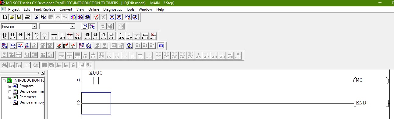
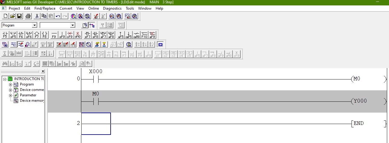
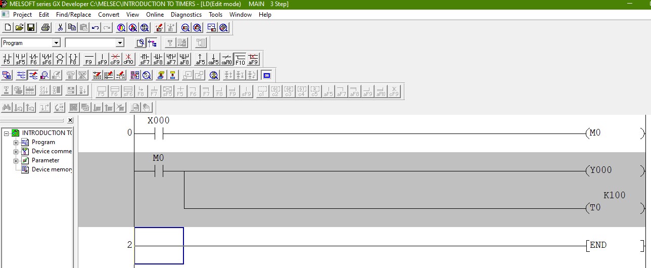
PLC ladder programming is one of the popular IEC programming languages used in the automation of systems. Learn the…
Industrial Manipulators Are one of the essentials of pick-and-place operations in the industrial setup providing an easy and efficient way…

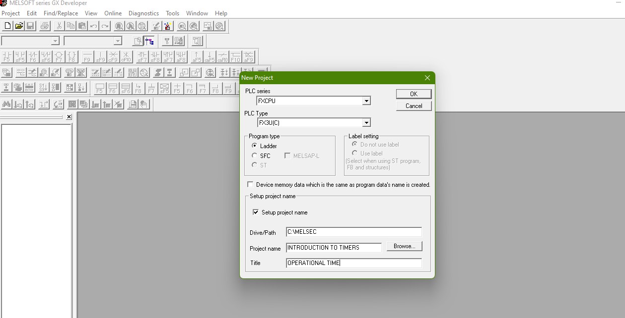
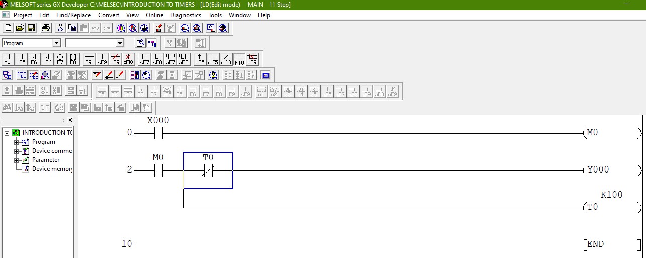
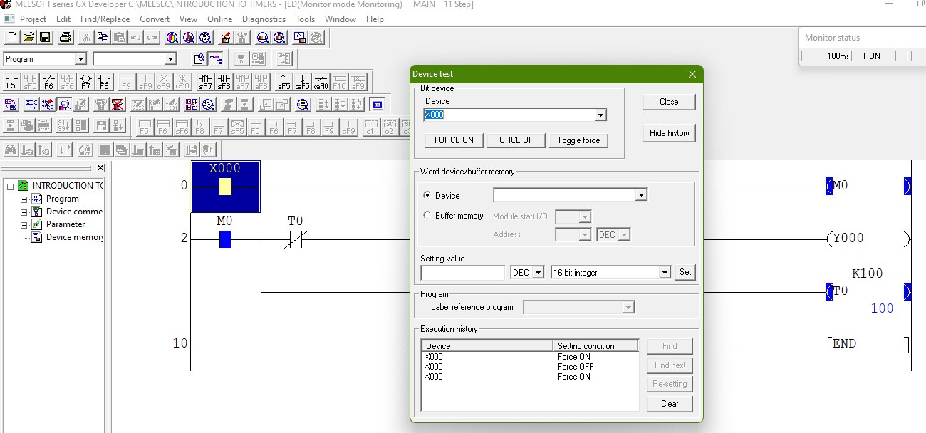
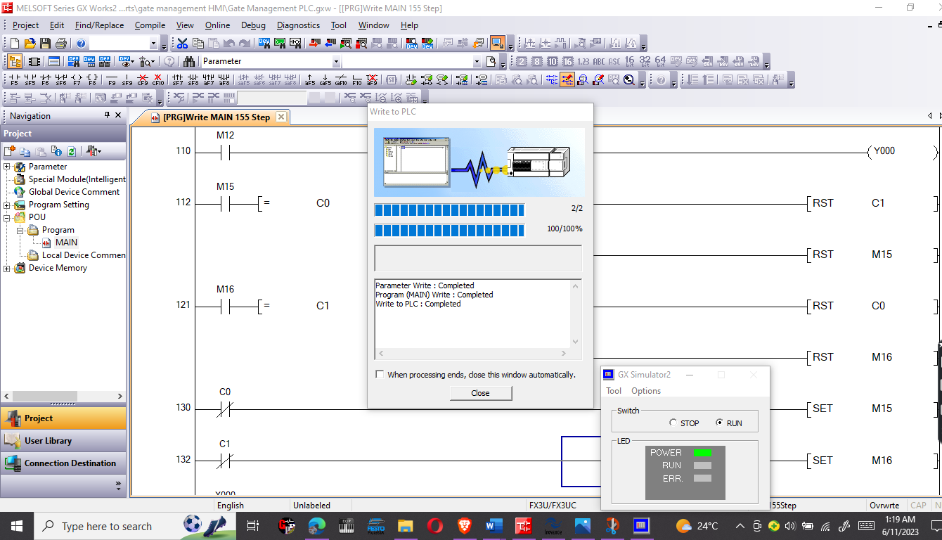
PLC programming in Mitsubishi’s FX series is made easy with the ability to read and write programs using a PC.…
Nice tutorial
Good job